
Full-Race's ELECTRONIC WASTEGATE CONTROLLER OVERVIEW

FULL-RACE ELECTRONIC INTERNAL WASTEGATE CONTROLLER BY DCCDPRO (USER GUIDE)

INTRODUCTION
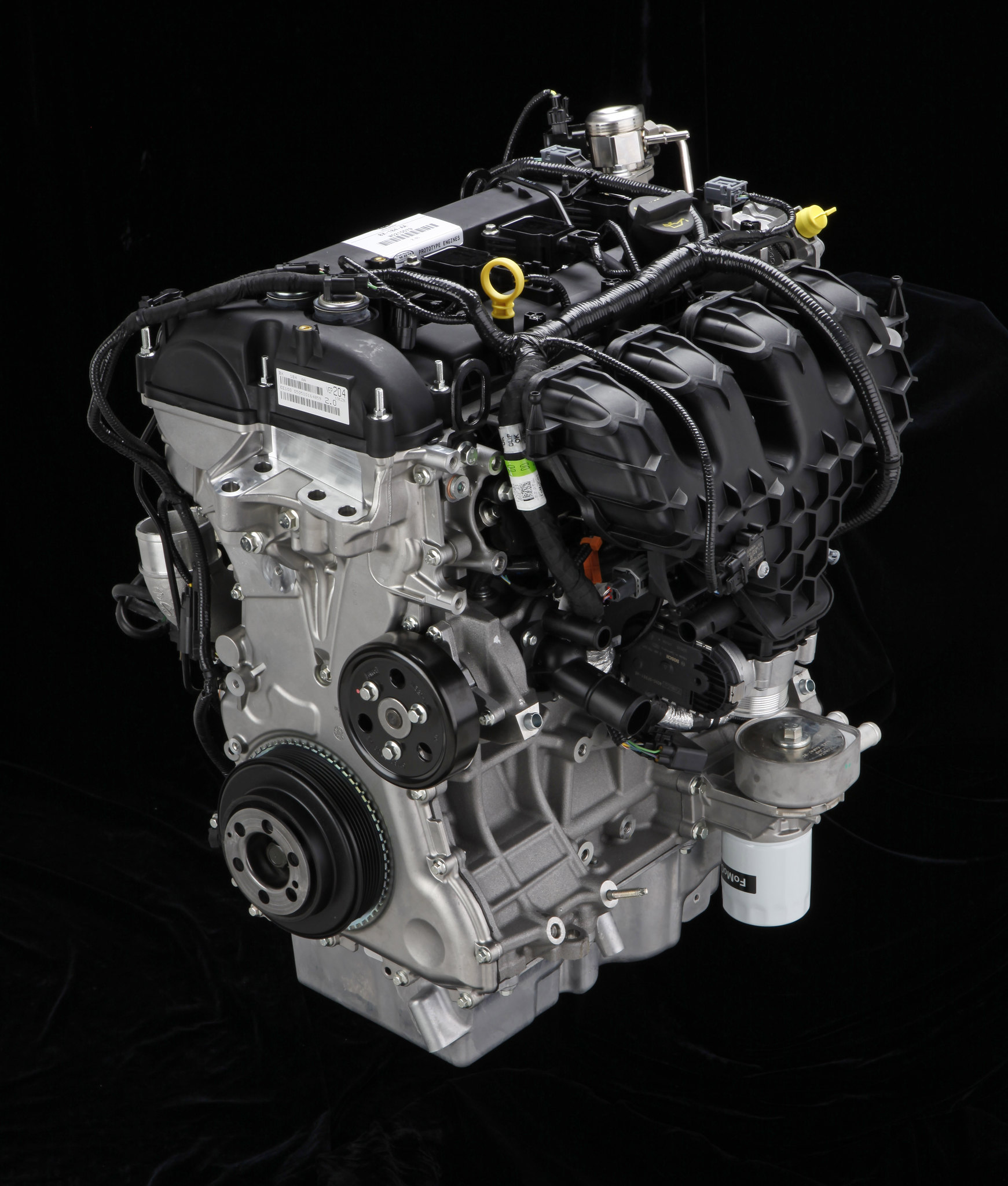
The Full-Race Electronic Internal Wastegate Controller is a DC Motor driver designed for Melco® linear wastegate actuators. It controls the opening and closing of the wastegate valve based on a PWM signal input and feedback from the wastegate position sensor coming from the wastegate actuator.

WASTEGATE CONTROLLER CONNECTIONS
Use Table 1 Main Connector Connection to determine SWITCH, ECU and eIWG connections.

INSTALLATION
The recommended location for the installation of the box is near the dash. Pass the signal cable through the firewall to the actuator. It is recommended to use the actuator’s OEM connector. Pin or Solder the wires to Power Cable according to the pigtails from the connector and insulate with heat shrink. If using the pin connections provided, make sure to tether the cable so the pins are not pulled due to shock and vibration.
B8: +12V Power Wire: The power wire should be connected to a spare switched power from the fuse box with a minimum 10 A capacity and fused accordingly.
A1: Ground: The ground connection must be made to solid body ground. ECU ground and Body ground should not be isolated.
B5: PWM Signal from ECU: Connect to engine ECU’s Actuator Control output PWM @ 1 kHz (5V digital or Open Collector). Note: This signal should not be lower than 5% (fully closed) and not higher than 96% (fully open)
Push-Button: The push-button (with a light ring as in Figure 4 LED and the push-button) is a panel-mount and can be easily affixed using the washer and nut provided. Make sure that the connections at the ‘Switch terminal’ are one-to-one after the installation of the push-button.
Caution
- Do not share the power line with other devices.
- Do not expose the unit to direct heat.
- Do not expose the unit to extreme vibration
- Please review Controller Operation (page 8) before proceeding.
- Use an electrostatic wrist band when installing the unit.
- Do not power the unit until installation is complete.
CONTROLLER OPERATION
Start-Up
Once power and signal cables are connected and power is turned on, the system by default is in Operation mode (shown below in Table 3).
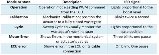
Calibration
Next, the mechanical gate closure mechanism must be initially calibrated before using the controller. Wastegate calibration is performed in Calibration Mode. After initial calibration is completed, the system will verify its calibration at every restart.
Sweep Cycle Mode
The controller arm continuously opens and closes the wastegate to visually ensure the mechanical system is behaving correctly.
Note: Electronic actuators do not tolerate any misalignment of the turbocharger. It is critical that the turbo is perfectly clocked and the actuator arm oriented to prevent any binding or misalignment.

CALIBRATION PROCEDURE
With unit powered on, follow these steps (or flowchart in figure 5) for calibration of the system.
- Press and hold the push-button for 3 seconds to enter the Calibration Mode.
- The push button’s LED starts flashing, and the actuator moves to the calibration position (wastegate fully closed).
- Perform mechanical adjustment. Set the arm length so that the actuator does not bottom out or top out on the mechanical stops (as recommended by the actuator’s manufacturer).
-
Press and hold the Push-Button again for 3 seconds to enter the Sweep Cycle mode. The actuator arm in Cycle mode continuously moves from fully close to fully open and back to closed.
- Visually Inspect mechanical joints for any binding in the linkage, and make sure the turbocharger and bracket are optimally clocked with the wastegate fully closing.
- Press and hold the push-button 3 seconds for the third time, to exit calibration/cycling mode and return back to Operation mode
Note: If after power is turned on, you notice that the LED in the push-button is blinking, the controller is in one of the ERROR states (motor error or ECU error mentioned in Table 3). Error states are described in detail on page 11 in the System Errors section. You can still calibrate the system in ERROR states by pressing the calibration Push-Button for 3 seconds to enter Calibration Mode.

SYSTEM ERRORS
Motion Error
Flashing of push-button LED with the frequency of 3 Blinks followed by a pause is an indication of a Motion Error. This error state is due to either blockage of mechanical movements by an external force such as the wastegate or a disconnect of actuator wires.
Once the blockage is removed or the actuator DC motor /sensor connections are fixed, the system error can be cleared by holding the push-button for 3 seconds. The system resumes in calibration mode to fix the mechanical maladjustment.
No ECU Signal
Flashing of the push-button LED followed by a pause is an indication of No ECU Signal Error. This error state is due to connectivity issues between the engine ECU module and the Wastegate controller. Once the connectivity issue is resolved, this error state automatically clears, and the system moves back to operation mode.
Optional Logging with C7: PWM Signal from ECU (Optional)
The C7 output produces a PWM equivalent of sensor's output for monitoring purposes. The C7 output is a linear map therefore 0-5VDC maps to 0-100% duty. The sensor inside the driver motor is providing a range of 0.2V to 4.8V at either end so it will translate to about 4-5% to 96-97% duty cycle.
Logging is possible if the logger has some low/high trigger to catch the rise of signal event and then start a timer to time until fall of signal. The duty cycle will then be divided by 202 mS (base signal frequency is 495 Hz).
ADDITIONAL RESOURCES
MHI Melco Actuator and Control System Diagram

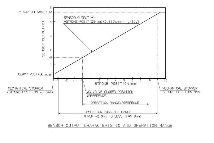
MHI Melco Actuator Setting Procedure
Move actuator rod to fully retracted position
Extend actuator rod until 3.5 ± 0.25mm displacement reached and record displacement and position sensor voltage
Install the linkage, then with the wastegate valve held tightly against its seat and holding the lower actuator rod nut, tighten the upper rod nut to 5.5 ± 0.8 Nm.
Extend the actuator fully and record displacement and sensor voltage.
Retract the actuator until the wastegate is closed, record displacement and sensor voltage then extend actuator slightly for shipping.
MHI Melco CTR Actuator
If you have questions about this product, contact us.
Resources
All Articles
For SHOP OWNERs
& KIT BUILDERs
Full-Race Motorsports is the most
trusted name in turbocharging.