
Scion FR-S, GT86, FT86, and BRZ Turbo Kit Installation

This article presents a few different installation options and “best-practice” tips specific to installing our EFR turbo kit in this engine/chassis combination. If this article helps you, please share it with others!

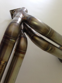
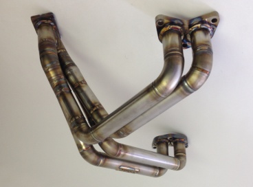
strong>Background: Full-Race turbo kits are based on the simple principle that turbocharged engines work best with an optimized and efficient exhaust side. Built upon the solid foundation of our exhaust manifolds and merge collectors, we use high grade stainless steel and robotically TIG welded runners for the strongest and highest quality welds in the aftermarket turbo industry. This particular FA Boxer engine design utilizes long runners and our trademark low-angle merge collectors for maximum flow and minimal pressure drop. From a performance standpoint, optimal flow and minimum pressure drop results allows for early spool, quick response and strong top end power. A stock motor with conservative tune using small frame EFR turbos on wastegate pressure and pump gas can achieve a safe and reliable 300-350whp. Increased power levels of 400+ and beyond can be reached with increased boost levels, fortified internals, and better fuel – limits depending on turbo size.
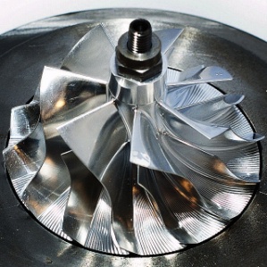
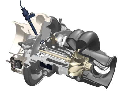
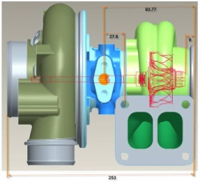
EFR turbos have reliably propelled everything from daily driven grocery-getters to LMP2 / Daytona Prototype championships and multiple Indycar seasons. Proven by providing years of reliable, consistent turbo operation at the highest levels of motorsport and street driving – with no hardware failures. Our EFR turbo kits are specifically designed for use with BorgWarner’s EFR (Engineered For Racing) turbos. BorgWarner Turbo Systems is the OEM supplier to many of the top automakers, and Full-Race’s technical partner for modern turbocharging. For an introduction to these turbos:
Tools required complete selection of metric combination wrenches, 3/8″ and 1/2″ ratchets with deep and shallow sockets, swivels/extensions, an impact gun (air or electric), a small cutting device (pneumatic jigsaw or electric 4.5″ angle grinder), an adjustable crescent wrench. In addition, RTV sealant is needed for the oil pan and high-temp anti-seize should be carefully applied to all exhaust side threaded and clamping surfaces; Exhaust manifold bolts/studs/nuts, vband surfaces/nuts, wastegate actuator lock nuts and bracket screws, etc they should all have anti-seize!! Depending on your oilpan configuration, you may choose to weld a fitting on the steel OEM pan or use an aftermarket aluminum oil pan with drain fitting already welded.


Parts needed in addition to turbo kit:
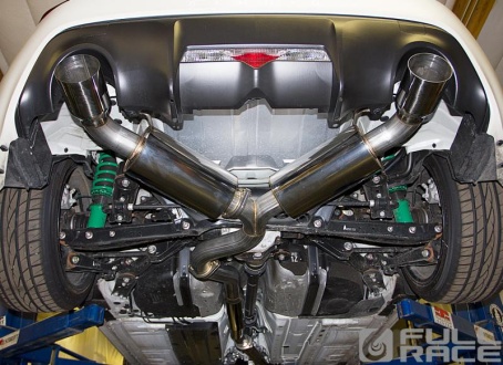
- 3″ Exhaust: Full-Race 3″ recommended http://www.full-race.com/store/exhaust-systems/scion-fr-s-toyota-ft-86-subaru-brz-3-cat-back-exhaust-system-1.html
- Clutch: Exedy, OS Giken, ATS & Across
- Engine Management: EmTron (standalone) or Ecutek (piggyback) are most popular
- Fuel Pump: Walbro 255lph or the Fat Bottom 400lph/450lph is an old and reliable favorite, the DeatschWerks 265 / 320lph are also recommended.
- Upgraded Port Injectors: ID1000cc or DeatschWerks 750cc
- Fresh OEM spark plugs gapped at 0.030″
Tuning you need an engine calibrator or “tuner” that you trust, who is familiar and experienced with tuning modern turbo engines. It is helpful to have someone local that is experienced to help with things whether oil drain TIG-welds, fuel pump baskets or help with tuning when you have any questions. There are also many excellent E-tuner options to choose from, where the tuner can email you calibration tweaks based on your logs. We’re happy to make a recommendation for you depending on your location and setup.
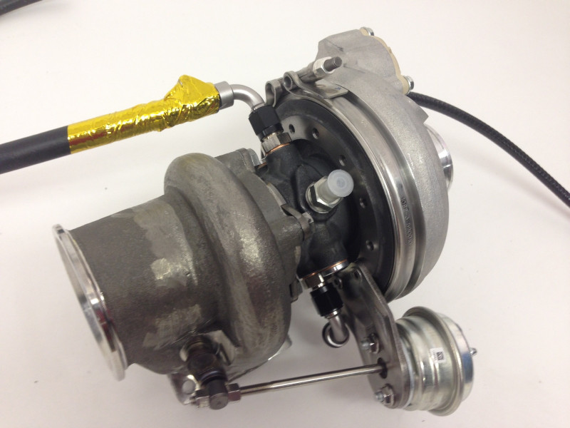
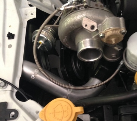
Step 1: Clocking the turbo and preparing for installation : Aftermarket turbos require you to “clock” the turbocharger center section and bearing housing upon installation to suit the application. Prepping your turbo for installation ahead of time can save hours during the install process. In the case of the EFR we also have a wastegate, BOV, coolant/oil feed and drain fittings and boost control all integrated into the turbo. This reduces the amount of parts needed for the install and means we must clock it into position for proper fitment, before taking the car apart. We suggest starting the install by “bench-assembling” the EFR turbocharger to reduce vehicle downtime – allowing you to get ready for the install before disassembling the vehicle. Take your time, starting this step a few nights before you plan to do the install is a good idea, since it will set the stage for everything else to come.

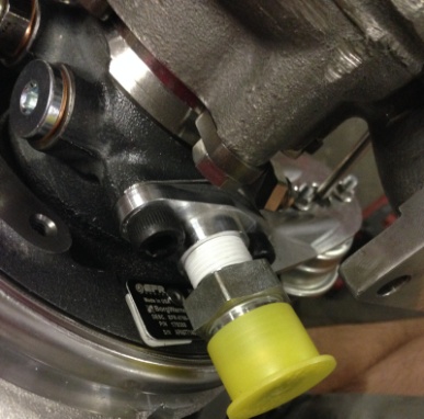
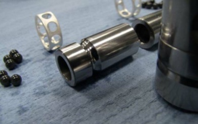
Step 1a: Clock turbo, install fittings: First remove the 3 screws which hold the actuator bracket in place. Next, slightly loosen the Compressor V-Band and the turbine housing bolts with cam-swivel locks so you can adjust the turbo’s orientation. Study these pictures below and replicate everything as closely as possible. Reference the coolant fitting locations (in on the bottom and out on the opposite side top) using the supplied aluminum -6AN fittings and crush washers. Make sure to use high temp anti-seize on all turbo hardware and the special high temp lock-washers included should remain as pairs – not be separated or lost. They will keep tension on the turbo hardware and make sure the gasket stays leak free, never allowing vibrations or heat cycling to loosen from the manifold.
Step 1b (optional): If you plan to use the EFR turbo’s speed sensor, now is the best time to remove the compressor housing and drill/deburr for the speed sensor probe: http://www.full-race.com/store/turbos/borgwarner-efr/borgwarner-efr-speed-sensor-kit.html
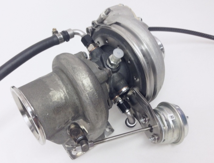
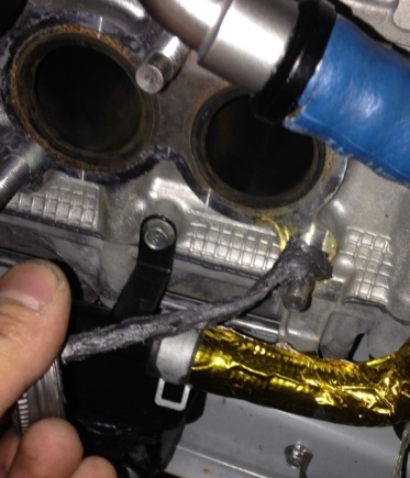
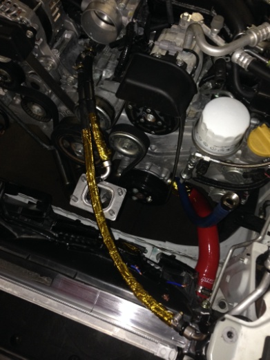
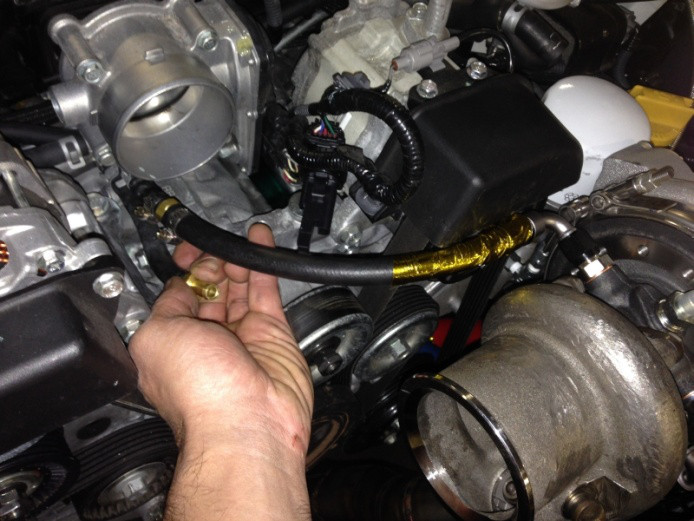
Step 1c: Once the turbo is clocked, Mount wastegate and bracket, using anti-seize for all threads – the Wastegate actuator arm must sit comfortably without misalignment or binding. Once it’s centered in the “happy place” the actuator arm position dictates the center-section-bearing-housing’s final resting position. After completing this step, you can slip the 3/8″ coolant hose over the -6AN 90degree hose end barbs and use the hose clamps to fasten them securely . We also recommend to wrap the coolant line behind the turbine housing with self adhesive gold foil, to protect from the manifold and turbine housing’s radiant heat.
The only fastener you will need to adjust later is the Compressor Housings’ vband nut (you can leave this just loose enough to rotate the housing by hand, but tight enough that it isn’t rattling or falling off (we will fully tighten it in the car later, along with the downpipe’s vband clamp).
Step 1c: install WG with bracket, setting the EFR wastegate preload: the IWG bracket for a B1 frame EFR (6258, 6758, 7163) is very simple: use the original BW bracket that comes with the turbo.
*Optional – For high horsepower builds, fitting larger B2 frame turbos (7064, 7670, 8374, 9180) to this engine/chassis will require the “B2-EFR offset bracket” for actuator clearance. the largest 62mm EFR8374 and 67mm EFR9180 needs this extra space. You can optionally use a variety of different aftermarket EFR wastegates to achieve youre desired range of boost targets. E-mail tech@full-race.com with questions on your application, we will be happy to make EFR wastegate recommendations based on the application, fuel used and target boost/hp level.
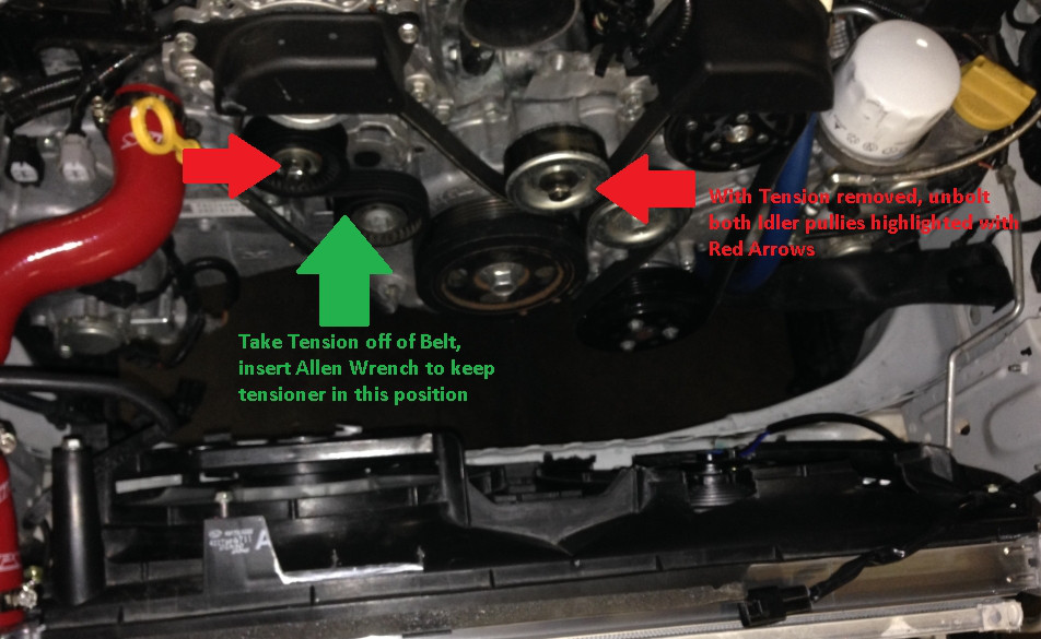
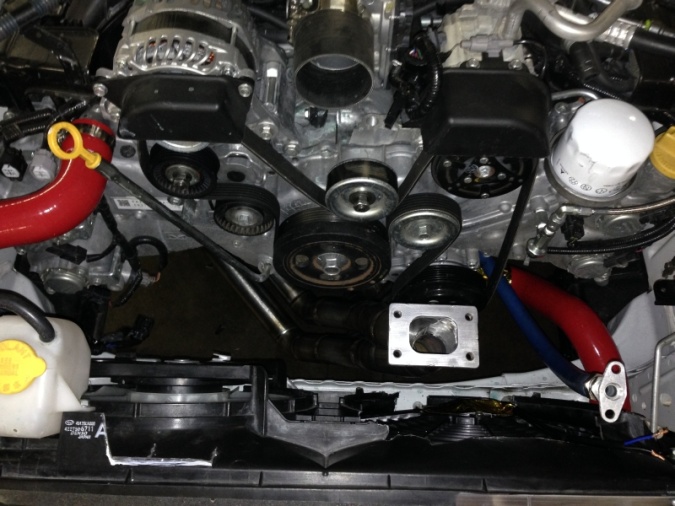
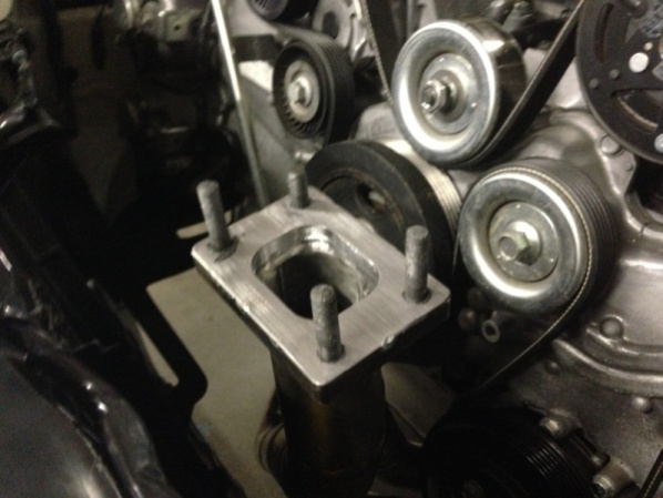
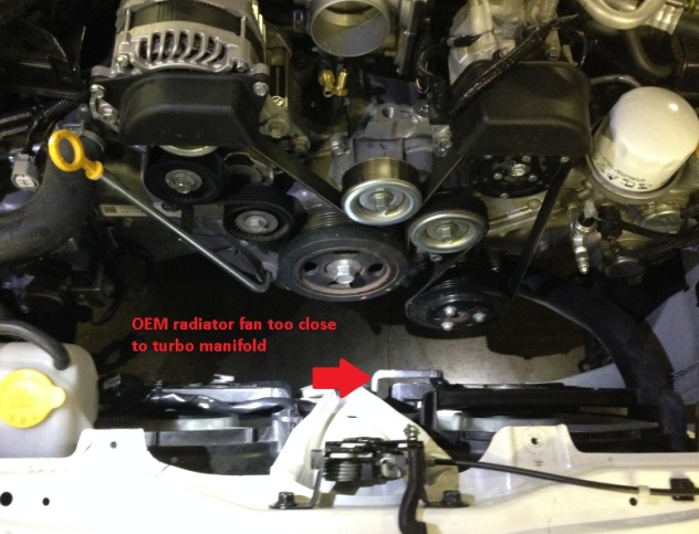
Step 2a: Accessory Belt and radiator hose heat-shielding: Now, install the accessory belt heat-shield. Put a wrench on the belt tensioner, to remove belt tension, and install an allen wrench to keep tension off the belt. Change the Bolts to Full-Race M10 studs, M10 couplings and M10 bolts.
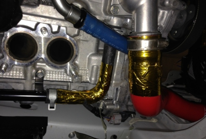
Step 2b: carefully apply the gold foil to the lower radiator hose (helping to protect from radiant heat)
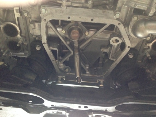
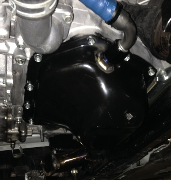
Step 3: Adding Oil Drain to Oil pan: This can optionally be done as step 2 if you have a second oil pan to prep, helping reduce downtime. You must unbolt the oil pan and remove it from the motor, to be sure all metal shavings are cleared before reinstalling with good RTV sealant.
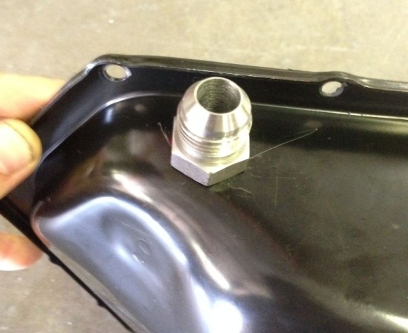
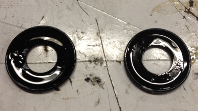
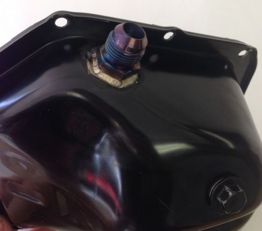
TIG weld the -10AN steel weld-fitting as shown, in the upper LH position on the pan. After finishing this step, clean it. Twice. NO METAL CHIPS!!! Apply RTV and carefully install the rubber Reinstall, and allow to cure:
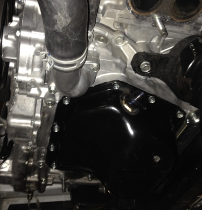
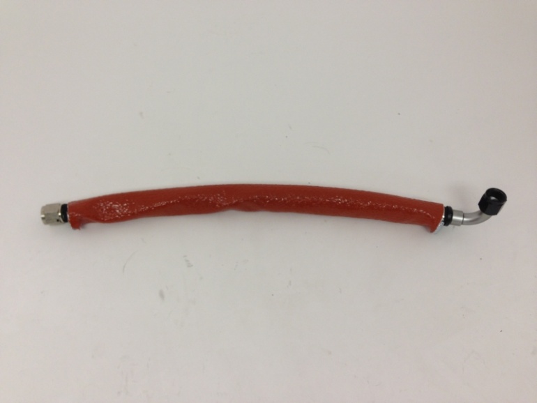
Then get the oil drain line together and in place. Use Clamps (not shown in photos):
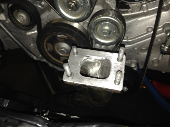
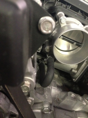
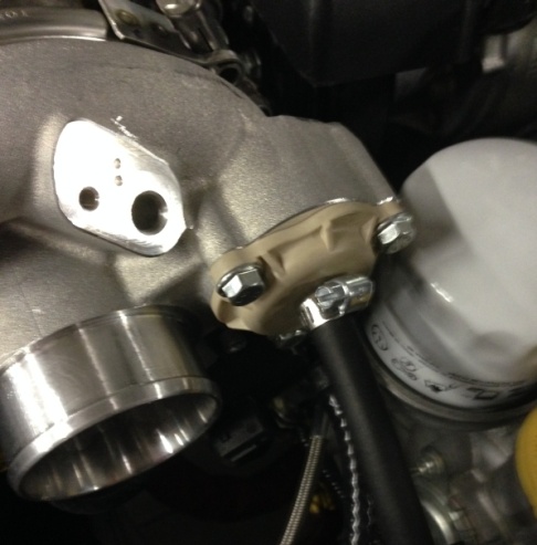
Step 4: Oil Feed: Remove M18 oil pressure plug next to throttle body. Replace with M18 to -4AN feed fitting. Do not use Teflon on the -AN fittings.


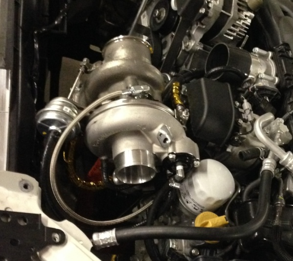
This is a good time to test fit everything and make sure you have the turbo clocked in the correct orientation + WG bracket fitting within the firewall’s space constraints. Take care that the turbine housing’s clamps are located properly in the locked position and fully tightened. Double check that all fasteners and mating surfaces have anti-seize and are fully tightened, the coolant fittings have crush washers and that only the steel drain fitting’s 3/8″ NPT tapered threads (at the turbo’s oil drain port) has Teflon thread sealant. If you’re certain the turbo is ready, its time to bolt it on!
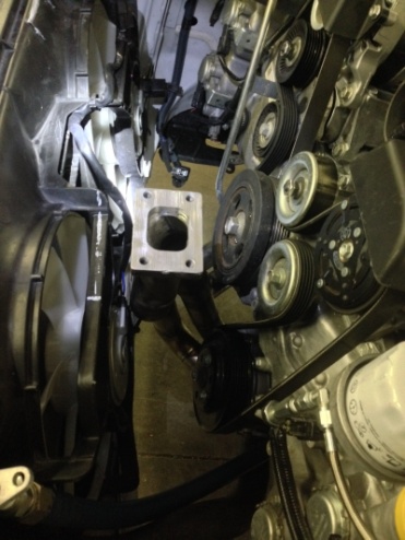
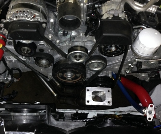
Step 5: Install Turbo Manifold, use antiseize & attach clocked turbo to Manifold: First, apply anti-seize to cylinder head hardware. Next, install the gaskets and turbo manifold, tighten hardware.

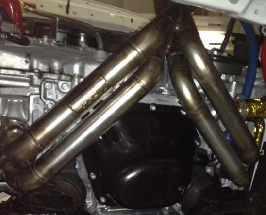
Next, orient the studs as shown – Insert the stud by the turbo’s WG flap upside down, apply anti-seize:
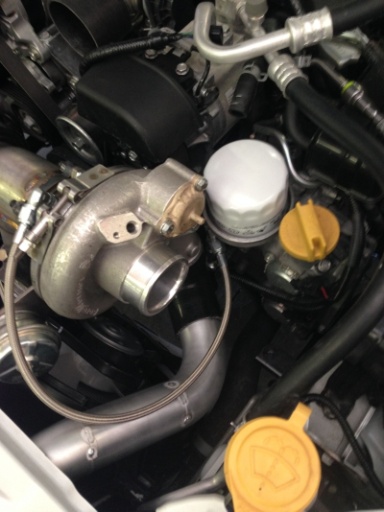
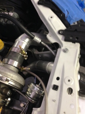
Now, you can bolt the clocked and oriented turbo to the manifold using the supplied hardware and lockwashers + gasket. Don’t forget the gasket!!!- pay special attention to the WG bracket orientation on the bearing housing, oil feed fitting and the coolant fitting positions in relation to each other.
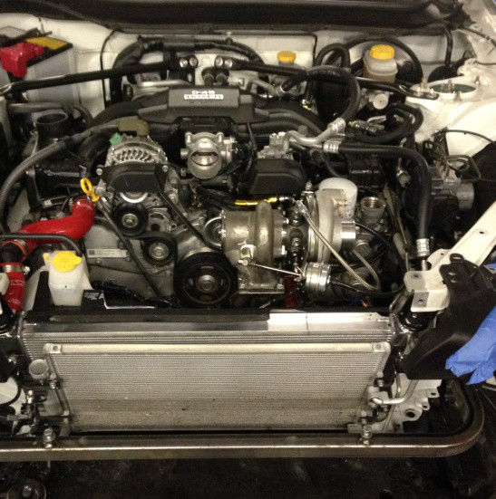
**note this photo shows the coolant lines which we will install in step 7**
EFR7670 show here, M10 hardware (not M8)
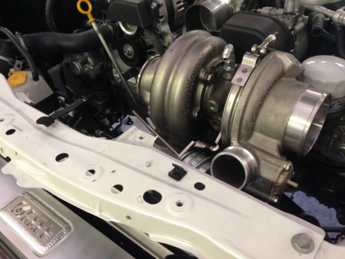

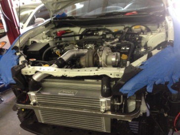
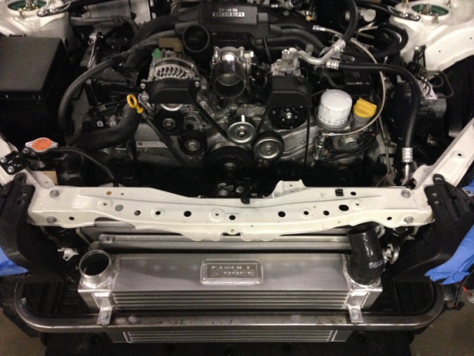
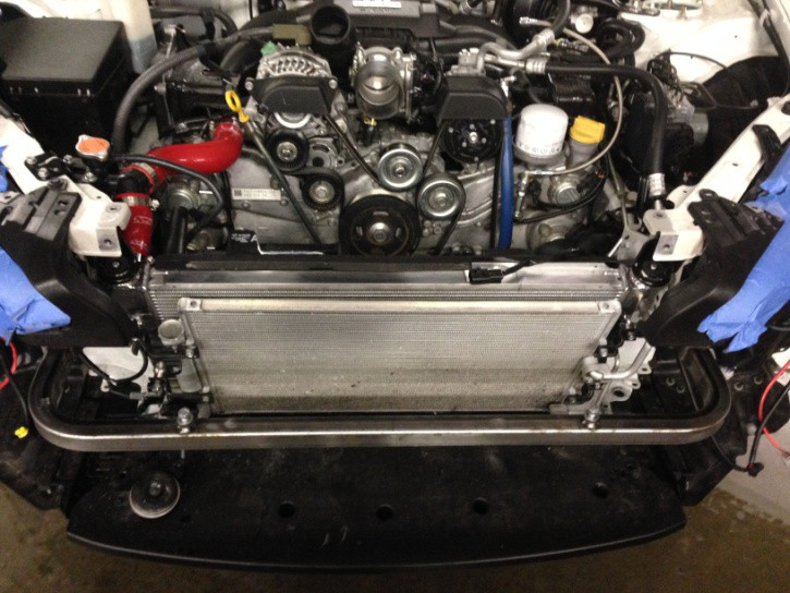
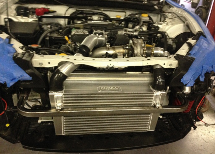
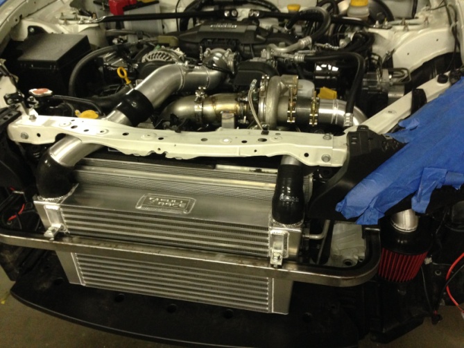
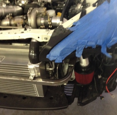
Step 6: Mount Intercooler Now is an ideal time to begin mounting the intercooler and piping, this will require trimming the non-structural sheetmetal headlight support for charge pipe clearance. Start by removing the Bumper cover – Unplug fog lights, unclip and remove bumper cover, unbolt bumper beam crash bar, and remove plastic shroud on drivers side in front of radiator/ac condenser. Then, install and bolt the Full-Race IC mounting beam in place of the stock beam. Re-use the stock bumper mounting hardware, making sure there is a clearance around all edges of the intercooler and that there’s nothing touching or rubbing the IC.
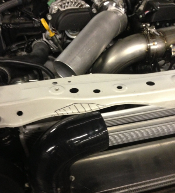
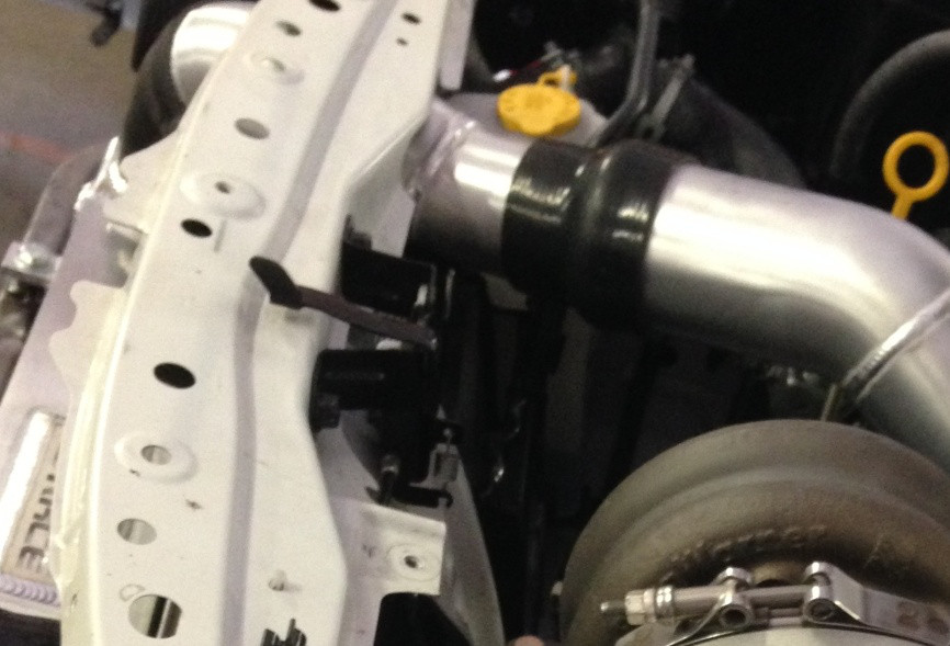
After the FMIC is mounted, you’re going to trim the non-structural sheet metal headlight support by the RHS cold pipe in order to fit the charge pipes through. Take a look at the pics below to get a good idea of how much you need to cut. Use a sharpie to mark off and notch the areas shown on the headlight support for cold-pipe clearance

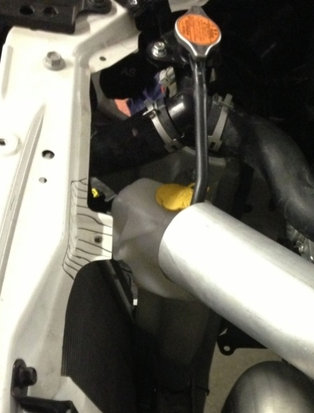
Next, do the same for the engine bay side:
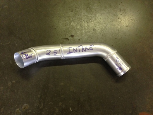
Step 7: Orient and Install Charge pipes and Intake Tube: Now is an ideal time to begin mounting the intercooler and piping, this will require trimming the non-structural sheetmetal headlight support for charge pipe clearance. Start by removing the Bumper cover – Unplug fog lights, unclip and remove bumper cover, unbolt bumper beam crash bar, and remove plastic shroud on drivers side in front of radiator/ac condenser. Then, install and bolt the Full-Race IC mounting beam in place of the stock beam. Re-use the stock bumper mounting hardware, making sure there is a clearance around all edges of the intercooler and that there’s nothing touching or rubbing the IC.
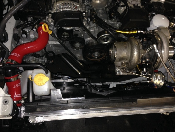
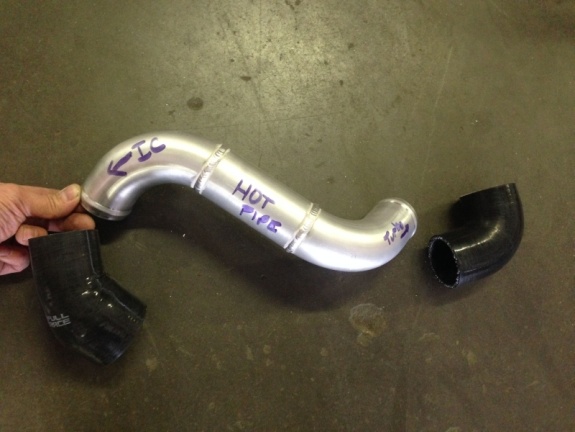
Next, fit the charge pipes. The piping is routed to give you the best turbo response and spool possible, so its well worth the effort to do this. Go slow, check alignment and do not over tighten the clamps. Its easiest to start from the turbo’s compressor 90 degree silicone elbow, go to the intercooler, then to the TB. Hotside piping is routed from the compressor 90 deg coupler outlet. This outlet should be positioned parallel to the firewall, pointing directly at the driver side fender. The charge pipe will go from this 90 to the IC’s top endtank.
This is a great opportunity to perform a boost leak test and check for any issues now, before going any further. Some excellent tutorials on how to test for boost leaks are on Youtube so we will not go into detail here.

Now that you’ve done this, tighten the Compressor Housings’ vband nut fully, it is time to go to the cold side charge piping. Make sure you have adequately clearanced the headlight support and nothing rubs.


Next – tighten all clamps (do not overtighten!) and Install + plug in your MAF/IAT sensor. Make sure the pipes are not rubbing on anything: hotside pipes/intake tube should not touch any of the wiring harness/brackets/hoses, and not on the frame or sheet metal. Coldside pipes should not hit the headlight support. If anything is touching, readjust. It’s ok to have slight misalignment in the couplers. Once everything checks out, tighten the clamps using 7/16″ deep socket (or 11mm deep socket)
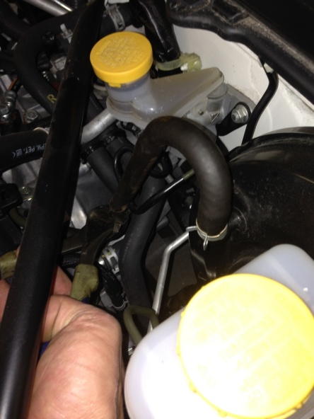
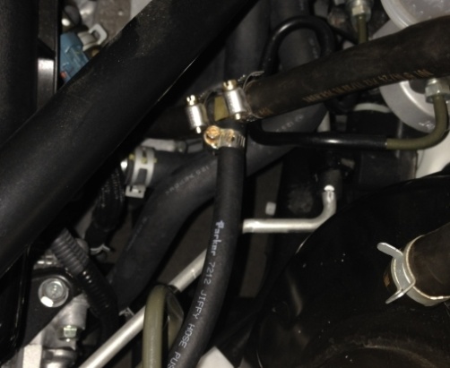
Step 8: Coolant lines: Tee into the 5/16″ throttle body hoses as shown


Connect Hoses and protect with Gold Foil
Interesting Fact: Coolant is used only for keeping heat out of the turbo’s bearings *after the engine is turned off*. When the engine is running, the oil is doing all of the cooling, the coolant has no purpose.

Install Radiator


Step 9: Hoses for BOV: – Set aside the supplied 3/16″ vacuum hose and brass Tee fitting for the BOV, and use a zip tie to keep it in place.
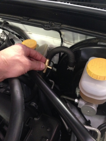


Attach the Boost control solenoid’s long vacuum hose to the wastegate’s upper nipple.

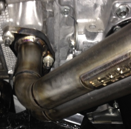
Step 10: Install Downpipe/Exhaust/02 Sensors: Loosely install downpipe, midpipe, and 3″ Exhaust at this time. Readjust the downpipe to make it fit perfectly with the exhaust mounted in place. Install Reinstall the O2 sensors and tighten the V-Band clamp. **We recommend that you coat the V-Band clamp’s threads and inner flange groove with high temp anti seize — this helps it tighten straight and the threads will last a long time!**Align all exhaust pipe components and fully tighten all hardware and vband clamps together, ensuring good alignment and no binding
Step 11: CATCH CAN there are 3 options for this:
1. Cap the port at the intake manifold and T both crankcase vents together to your Catch can inlet. Run a single outlet from the catch can to the pre turbo intake tube. This will always pull a vacuum on the crankcase, and it will not smell. Recommended for street cars)
2. Cap the port at the intake manifold and vent both ports to atmosphere – Upside is absolutely zero blow by will be going back into the intake tract. Downside is it can smell. Recommended for track cars or higher HP builds.
3. Run no catch can (like factory) OR a dual can setup. Not recommended because you will have a MAF leak at idle, and the tuner will need to rescale the MAF to account for the vacuum leak present when manifold pressure is less than atmospheric (ie: idle) – unless a check valve is added
Step 12: Prime Engine and Turbo with Oil pressure, prep for startup: Fully tighten the oil return, coolant feed and coolant return fittings then -> *ADD ENGINE OIL !!! *
A properly primed and leak-free oil feed and drain line are crucial to proper turbocharger health and performance – Triple check your oil fittings at this point since we want the turbo to immediately receive oil pressure upon engine startup. Check -4AN 90 degree oil feed to engine side – make sure it is tightened and will not leak and also tightened at turbo side without rubbing the stainless hose on anything. Check all hose clamps are tightened.
At this point the entire turbo kit is installed, and there should be no extra parts. Now is a good time to look everything over and make sure you are 100% satisfied with the connections and plumbing before starting the engine. There should be no loose bolts, no leaks and nothing rubbing. Fill the engine with oil (full synthetic!!) and with no spark or fuel (plugs disconnected) – so the engine can not fire – turn the key to the start position and let the engine turn over, building oil pressure and supplying to the turbo. After 15-20 seconds of cranking, check the oil level in the oil pan and make sure there is oil flowing into the turbo. Fully tighten the oil feed line and get ready to finish the fuel system and start the engine.
STEP 13 Misc: Reinstall Battery, Bumper Cover and Final Details: Fuel Injectors, Fuel Pump, Engine Management and any Gauges:
-Install the pigtail plug on the BCSV if you plan to connect to the boost control solenoid. If no boost control is desired (minimum boost, WG spring pressure) an unplugged solenoid means you will simply be running low boost all the time, which is perfectly safe for starting with and troubleshooting.
-Install Fuel Pump
-Install Fuel Injectors
-Spark plugs heat range 8 or heat range 9 NGK iridium spark plugs
-Turbo blanket (optional)
-Wire BCSV to evap plug
-Install clutch
-Check coolant and oil levels
-Double check that the heatshield at the serpentine belt is fully tightened
-Lastly, consider adding a catchcan between the PCV vent and the intake nipple
Resources
All Articles
For SHOP OWNERs
& KIT BUILDERs
Full-Race Motorsports is the most
trusted name in turbocharging.