
Subaru Rotated Intake Manifold
Instructions for Rotating the Subaru STI Intake Manifold
Parts Needed:
 GATES K050340 BELT (1) |
 THROTTLE BODY SPACER (1) |
 OEM THROTTLE BODY GASKET (2) |
 EXTENDED M6 HARDWARE (4) |
|---|---|---|---|
 |
 |
 |
Step 1
Remove the intercooler, charge piping, upper intake manifold, TGV bodies, and turbo inlet tube as described in the factory service manual.
 |
 |
|---|
Step 2
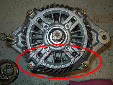
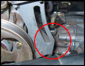
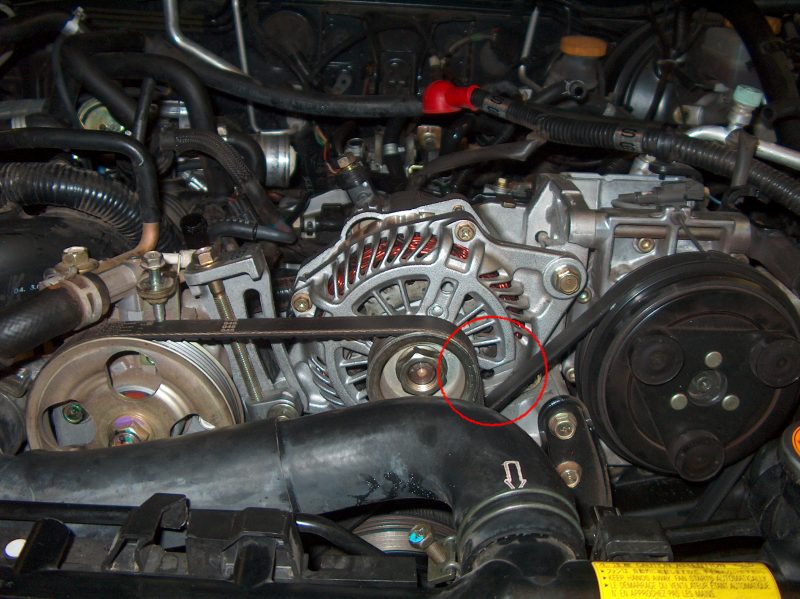
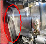
Remove the alternator as described in the factory service manual. Trace out the area on the face of the alternator from which material will be removed (circled in red); if you are unsure of where to remove material from, use the template included with your kit.
 |
|---|
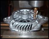
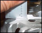
Fixture the alternator on your workbench (or mill) and remove approximately 7/32″ of material away from the face of the alternator. It is recommended (but not necessary) to use a mill to machine the alternator, however a 4 1/2″ angle grinder, pneumatic die grinder or Dremel tool will also work. NOTE: TO AVOID MACHINING THE ALTERNATOR YOU CAN USE A 2007 MODEL YEAR SUBARU STI ALTERNATOR.
 |
 |
|---|
Cut or “notch” the bottom of the alternator bracket so the alternator can sit lower in the bracket. A 4 1/2″ angle grinder, pneumatic die grinder or Dremel tool will work just fine.
 |
 |
|---|
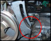
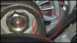
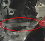
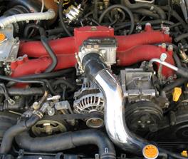
Reinstall the alternator using the supplied belt (Gates # 050340). Check for adequate clearance from the A/C belt to the alternator (circled in red). Be sure that enough material was removed in step 2 to eliminate the possibility of the belt contacting the alternator.
 |
 |
|---|
Step 3
Remove throttle body from intake manifold. Rotate the throttle body 90 degrees in the counterclockwise direction from the stock configuration, and re-install the throttle body using Full-Race throttle body spacer and extended hardware (M6). We recommend using new gaskets (Subaru PN#16175AA243) on both sides of the spacer to prevent any leaks.
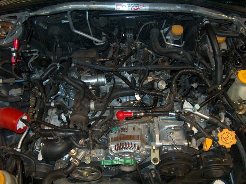
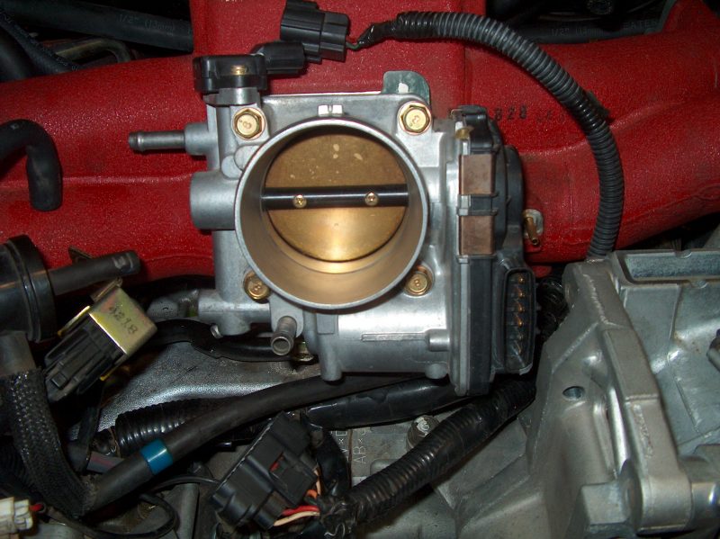 STOCK TB CONFIGURATION |
 SPACER AND GASKETS INSTALLED |
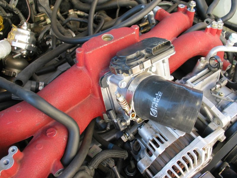
 TB ROTATED 90 DEGREES AND SPACER/GASKETS INSTALLED |
|---|
Step 4
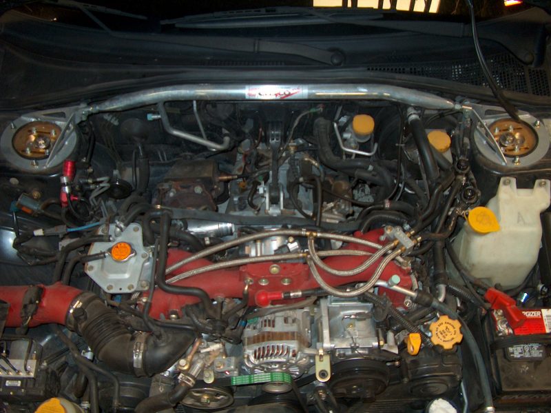
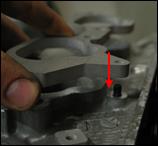
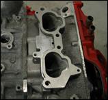
Place one Full-Race intake manifold spacer on each cylinder head as shown below. Use the included gaskets (Subaru PN#14035AA421) on both sides of the spacer to prevent any leaks. Next, carefully lower the intake manifold back into position with the throttle body facing the front of the car.
 |
 |
 |
|---|
Step 5
Following the instructions in the factory service manual, completely re-install the TGV bodies and the intake manifold in the rotated configuration.
 |
|---|
NOTE:
This install should be performed by an experienced and competent mechanic. Before starting the engine, verify that all vacuum lines, fuel lines, and coolant lines have been properly re-routed, and that all electrical connections have been correctly re-established before moving on. Some of these connections may need to be lengthened, shortened, protected, or removed depending on your specific application.
RECOMMENDATION:
It is recommended that the Full-Race reverse-mount intake charge piping and front mounted intercooler be used with the intake manifold in this configuration. Full-Race charge piping is specifically designed for this application and engineered to allow high velocity and minimal pressure drop of charge-air within the system.
 |
|---|
Resources
All Articles
For SHOP OWNERs
& KIT BUILDERs
Full-Race Motorsports is the most
trusted name in turbocharging.