
Evo X Turbo Install

Full Race Evo X 4B11T Twin Scroll Turbo Kit Install
Background
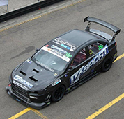
Since 2003 Full-Race has placed an emphasis on the development of our Mitsubishi Evolution turbo upgrades, ensuring that our customers get the cutting edge performance and reliability they’ve come to expect from Full-Race. Our legendary turbo manifolds surpass the industry standard for high-end exhaust manifold design and fabrication. Full-Race’s twinscroll and singlescroll turbo kits are proven from world class time attack applications to rally and pikes peak / hill climbs.


EVO X Turbo Kit Installation
The hardest part of any turbo install is knowing what to do. The point of this article is to shorten the learning curve and make it possible for anyone with basic hand tools and enough knowledge to do a proper installation on the Full-Race EVO X EFR turbo kit, the first time. There are many ways to do a turbo install, this article presents a few different options and some “best-practice” and tips specific to this engine and chassis combination. If this article helps you, please share it with others! We will update this page as time goes on. In order to successfully remove and replace your turbo, it is essential to have the proper tools to make the installation as smooth as possible. Before beginning any work, we recommend you review the factory service manual and verify you have everything needed before starting. If you know how to remove the stock turbo without needing us to explain it – you can handle this install. If you have no mechanical experience this is not for you. Keep in mind that because the turbocharger is behind the engine – certain precautions must be taken with respect to heat and plumbing, so it’s important to install things properly the first time and ensure no hoses or lines are touching the manifold. While this kit can be used with other turbochargers such as garrett, precision, comp or otherwise they would require external wastegates. Full-Race engineers believe the twinscroll EFR turbochargers are the ideal combination for this chassis and engine. Please take the time to read through this article and familiarize yourself with all the steps so the installation goes smoothly.
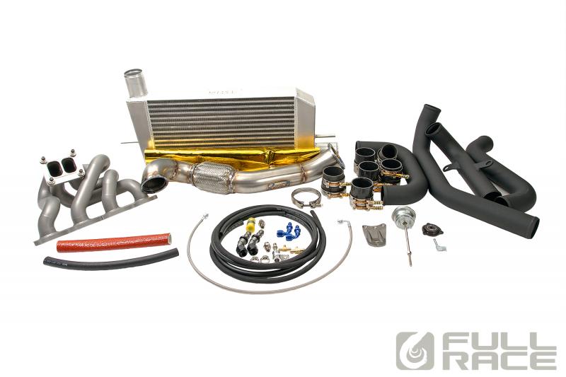
Full-Race EVO X Turbo Kit Overview
The Full-Race turbo kit consists of…
-
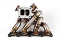
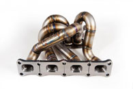
- Evo X Turbo Manifold – Hand fabricated, robotically tig welded. Available in internal or external wastegate versions.
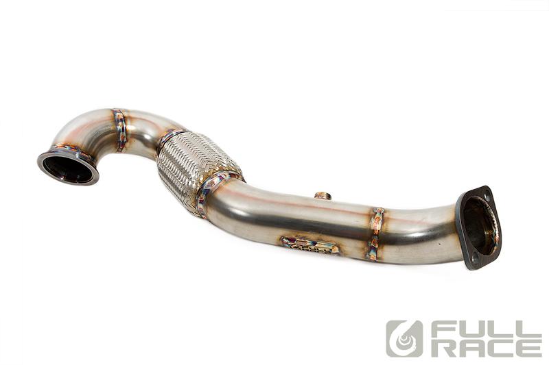
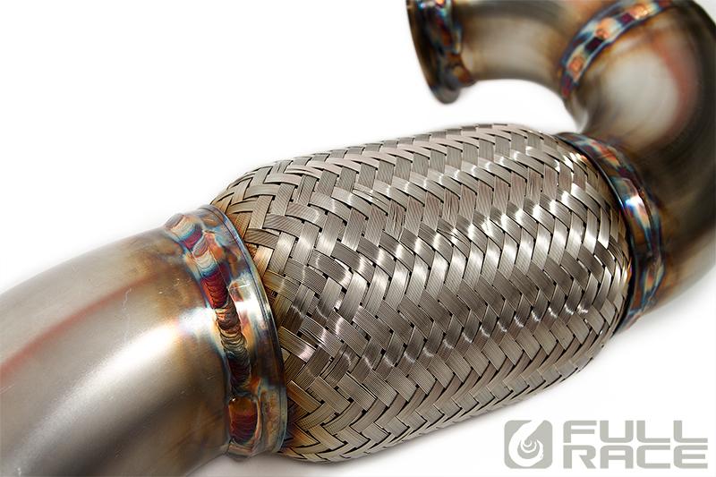
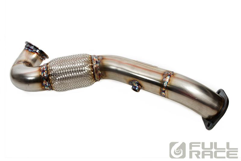
- Evo X Downpipe with flex section & O2 bung (bolts up to any cat-back exhaust)
- Aluminum BOV plate w/ 90 degree fitting
- 3.5″ MAF Intake (Increased HP Capacity) & Air Filter (no BOV recirc needed due to EFR turbocharger)
- Aluminum Charge piping, durable black coating, no BOV flange
- Thick-ply Silicone couplers and constant-pressure T-Bolt clamps
- BW EFR turbocharger w/ EvoX high boost wastegate actuator kit
- Lines & Fittings
- Inconel Turbo Attachment Hardware
Getting Started
Installing a turbo kit requires a basic understanding of cars and turbochargers, a safe working environment and proper tools. Experience with previous turbo vehicles helps but is not mandatory. A turbo kit install is not a good idea to rush into blind – prepare mentally by spending some time to learn about your turbo and read the EFR training manual. Get a good selection of tools and equipment to tackle the job. If you’re a ‘noob’ and scared of messing something up, don’t stress – Take it slow and do some research, everyone starts where you are. For basics try reading: Maximum Boost by Corky Bell and Street Turbocharging by Mark Warner.
Tools required are about the same as doing a clutch install (plus a few extras). A good selection of metric combination wrenches, 3/8″ and ½” ratchets with deep and shallow sockets with swivels/extensions, etc. In addition, high-temp anti-seize should be carefully applied to all stainless steel threads and clamping surfaces such as: Exhaust manifold bolts/studs/nuts, vband surfaces/nuts, wastegate actuator lock nuts and bracket screws, etc always use anti-seize for all threads and vband surfaces on the hotside of your turbo system.
Step 1: Prep the EFR Turbo for Installation
Aftermarket turbos require you to “clock” the center section and bearing housing to suit the application. In the case of the EFR we also have a wastegate, BOV, coolant/oil feed and drain fittings and boost control all integrated into the turbo – this reduces the amount of parts needed for the install and means we must clock it into position for perfect fitment- prior to attaching the turbocharger to the manifold. Before taking the car apart, prepping the EFR turbo for installation ahead of time saves hours on the install process. Take your time with this, since it will set the stage for everything else to come.
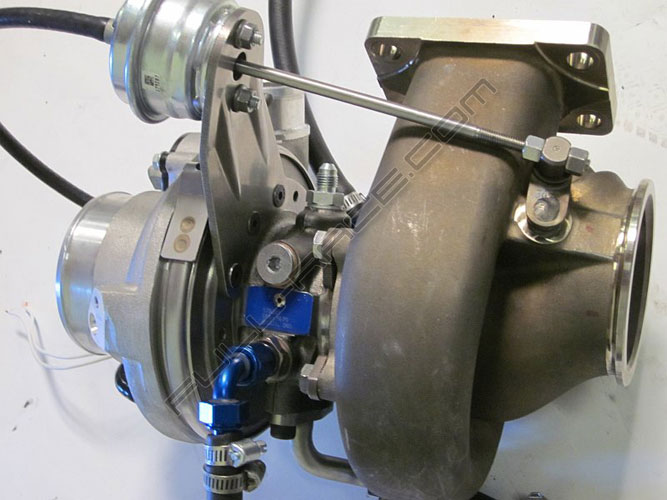
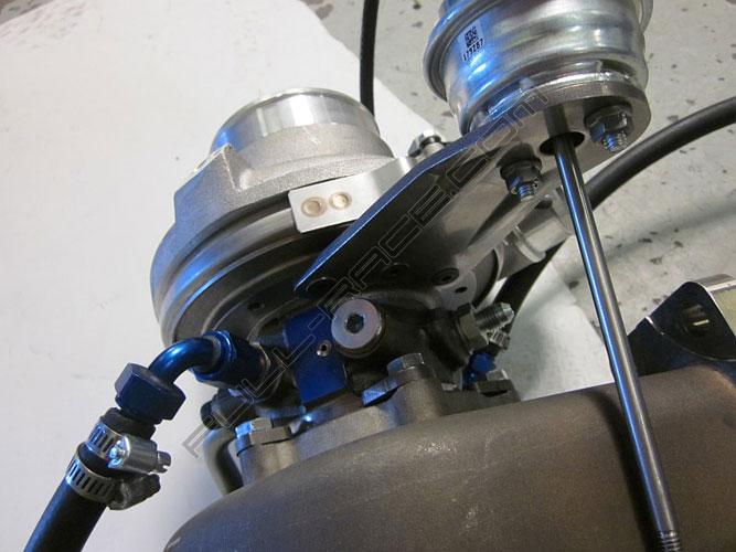
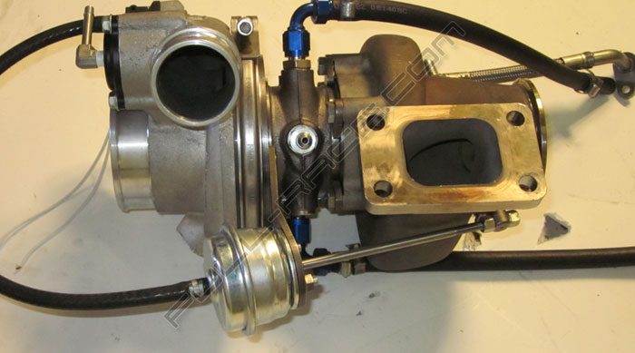
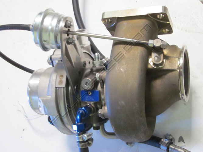
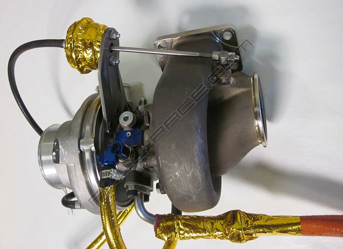
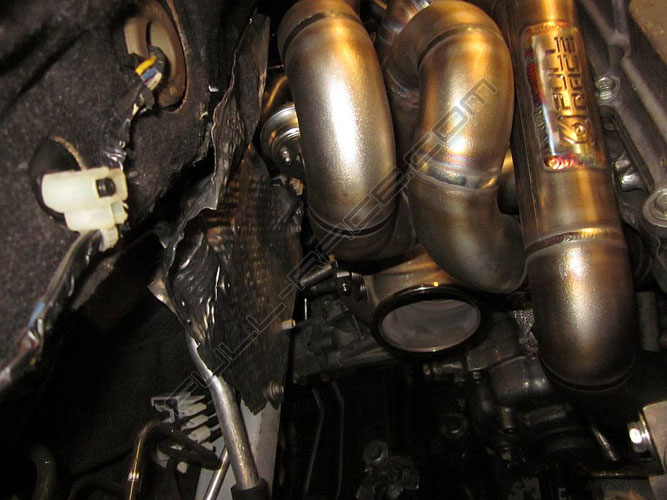
Step 1a: Loosely Clock turbo to match these photos, install fittings:
Identically duplicate this turbo clocking position shown above. Reference the coolant fitting locations Firewall side: in on the bottom VS Engine side: coolant out on the top. Use the supplied aluminum -6AN fittings and crush washers. Make sure to use high temp anti-seize on all turbo hardware.
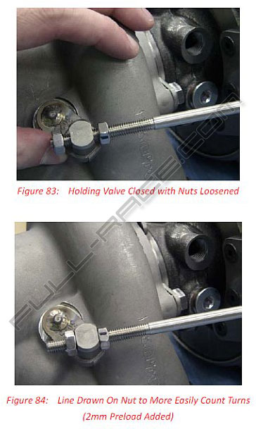
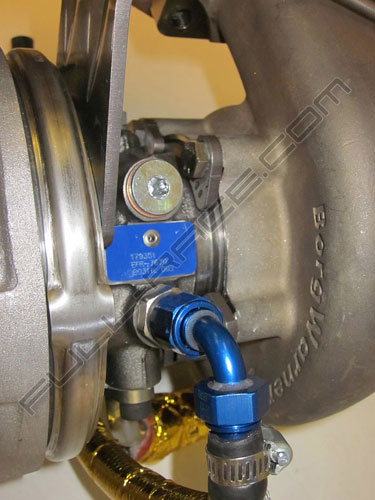
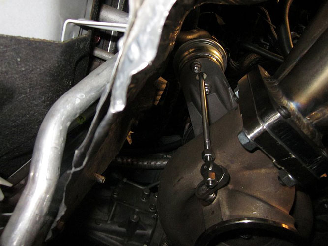
Step 1b: Internal Wastegate Actuator
For EFR internal WG installs on Evo’s, you must use the high boost canister part number 179287, included with the turbo kit. This is a particularly important step if using the internal wastegate configuration EFR turbo since the Wastegate actuator’s alignment will literally dictate the position of the bearing housing’s center section. You want to leave the center section:turbine housing connection a little “Free” to rotate, allowing the wastegate actuator arm to “settle” in the proper location. There should not be any misalignment on the wastegate actuator arm and you must use the supplied B2 EFR wastegate bracket for proper fitment.
Note: We *strongly* urge you to apply high temp anti-seize to the WG actuator threads so it is easy to service in the future!!
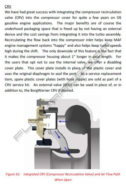
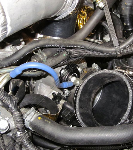
Step 1c: Full-Race EFR-BOV cover
The EFR turbo’s CRV (aka BOV) is a simple and highly efficient way to blow-off excess boost between shifts. The thermoplastic cover must be removed and replaced with the Full-Race 90 degree fitting plate. This allows for vacuum line clearance away from the MAF intake tube and is stronger than the original thermoplastic cover.
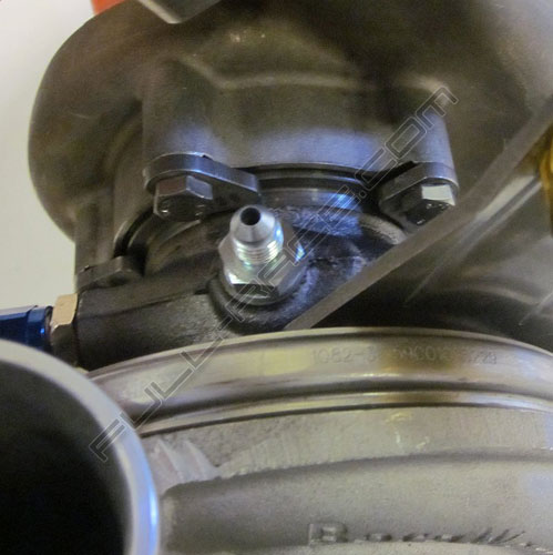
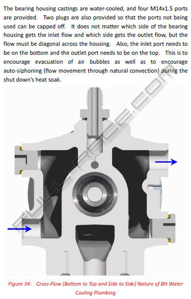
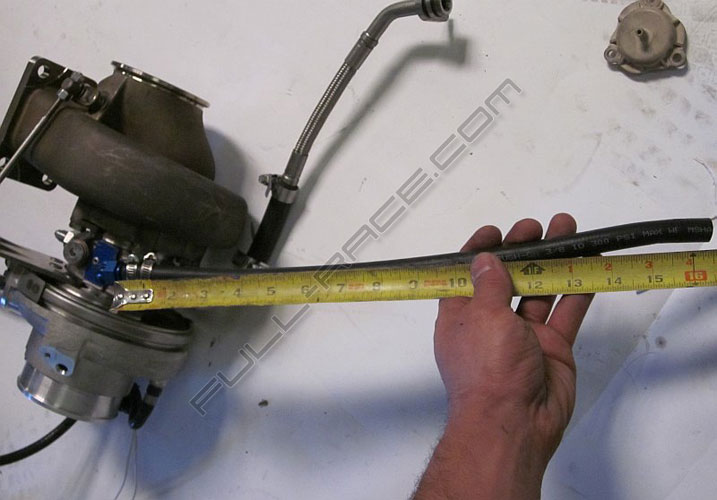
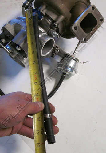
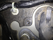
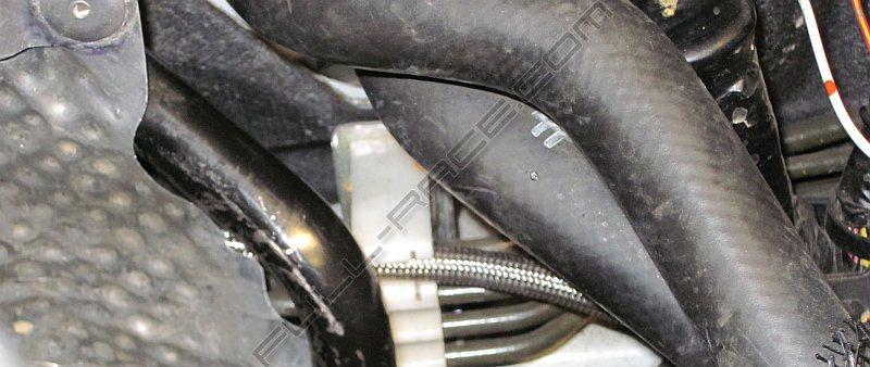
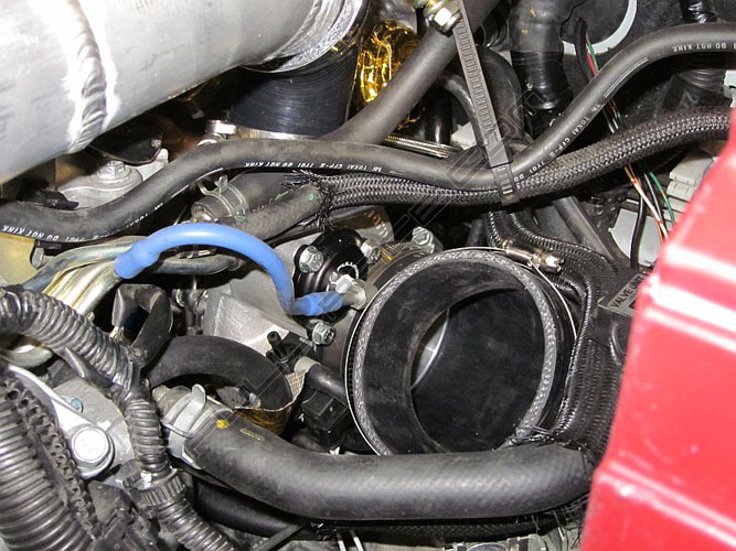
Step 1d: Coolant Lines
Take note that the bottom port is to be used as the “coolant feed” and the opposite top port is to be used as the “coolant return” back to the engine. The reason for this is that after the engine is shut off, we still want coolant circulating through the turbo! Because heat rises, the heat energy will keep the fluid circulating despite the water pump not turning. Please note how we have them oriented, and ensure yours is done the same way.
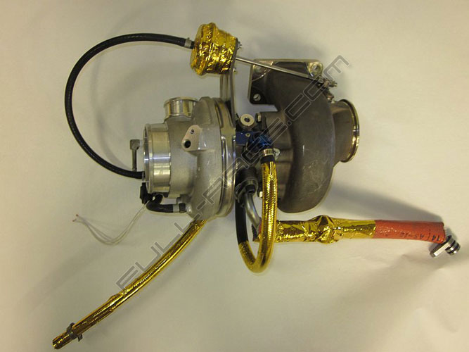
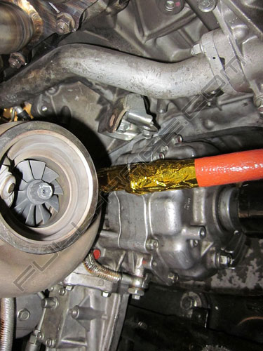
Step 1e: Heat Protection — Gold Foil & Firesleeve
The components we want to take extra precautions with in protecting from heat are the water hoses, oil lines and wastegate actuator. Because the Oil feed line is located behind the stock Evo X heatshield there is no precaution necessary. Be sure to gold foil everything shown in these photos.
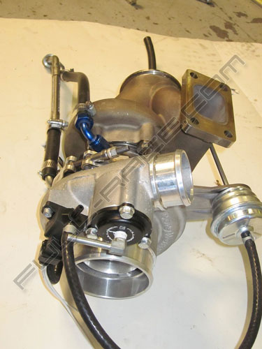
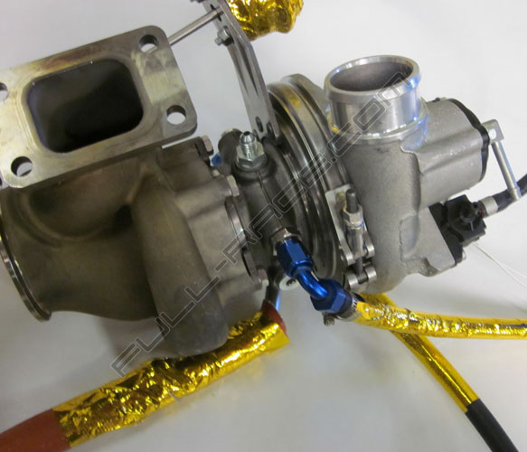
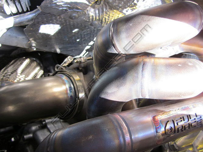
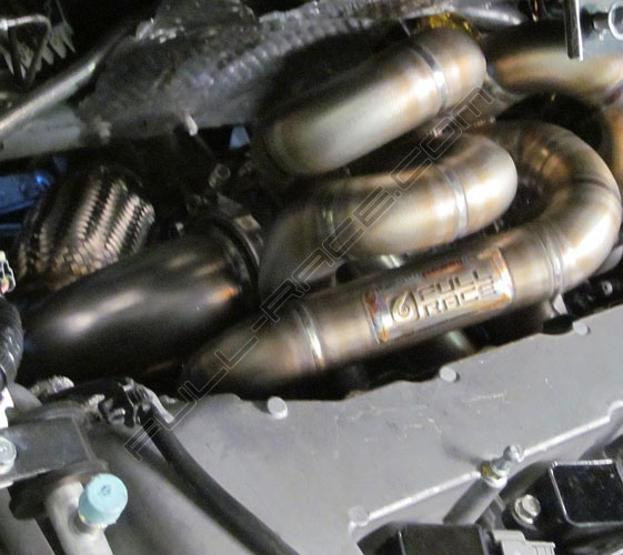
Step 1f: Tighten Turbo Components
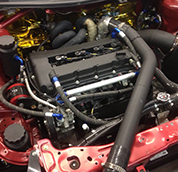
Now it is time to start tightening down all the turbo components and ensure that each hose and fitting are in the correct location. Weve photographed every angle to make it easy for you to get everything oriented properly and ready for. Make sure that your turbo matches these photos!
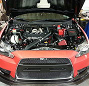
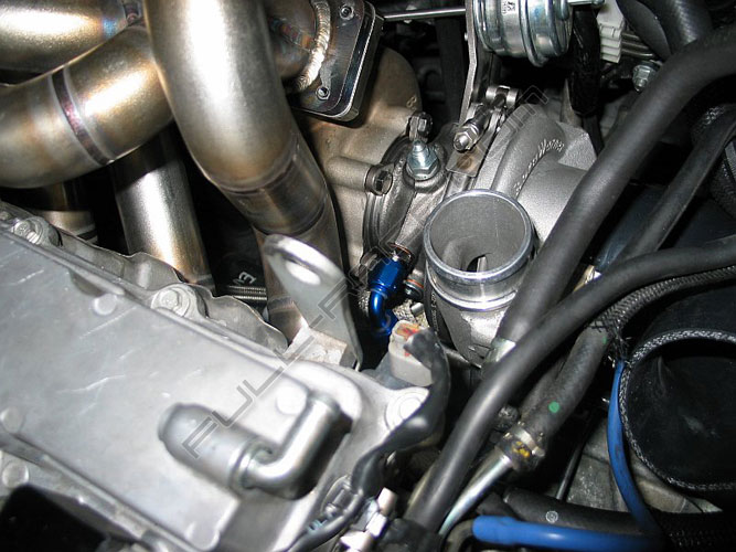
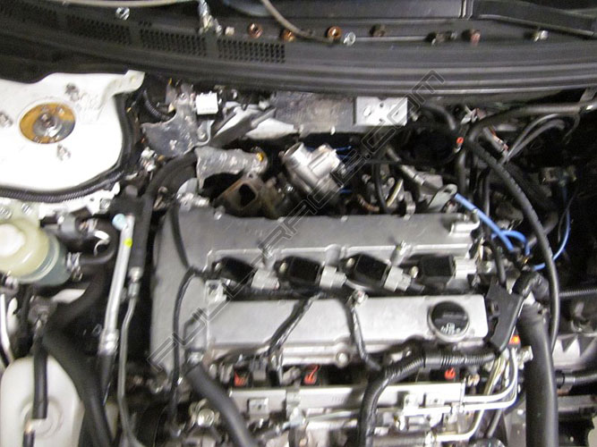
Step 2: Prep Engine Bay
Before starting any work always disconnect the battery as a safety precaution. Get the vehicle in a safe place where you can access the downpipe, exhaust and turbocharger. Jack stands are a must if you do not have access to a lift.
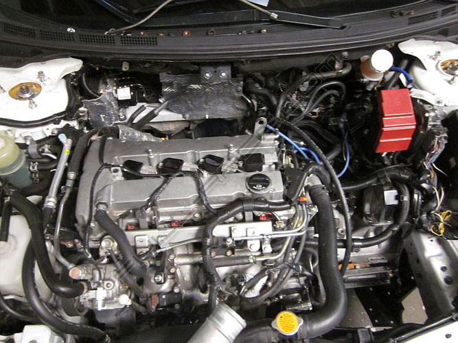
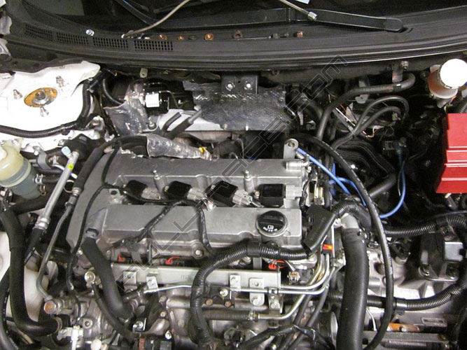
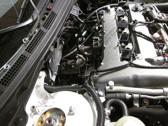
Get the engine bay cleaned and prepped for the install. Start by removing the Strut tower bar, charge pipes, Turbo, manifold, downpipe, oil lines, water lines, vacuum lines, BOV, charge pipe, MAF Housing, Air Filter, etc.
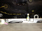
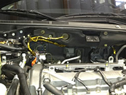
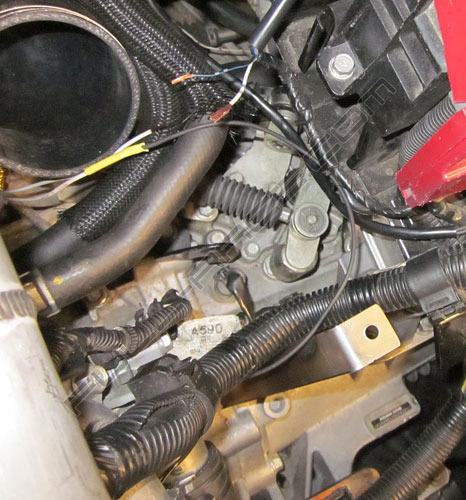
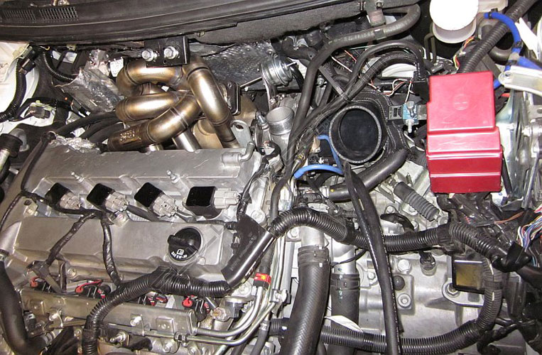
Step 3: Wiring heat Protection
Next we have to protect all the wires behind the motor by wrapping with the self-adhesive gold foil. We like to use a paper cutter and cut the foil into 1″ strips, then wrapping that like a ribbon around the harness. Most importantly, wrap the wires which run along the firewall AND the ABS harness under the cowl since they would be close to the turbine housing and downpipe.
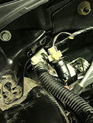
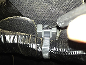
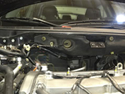
Once everything has been removed you will have access to the wire harness. In the rear passenger side corner of the engine bay release the clips mounting the harness to the body using needle nose pliers. Along the firewall you will find a series of clips that are mounted to protruding tabs as seen in the photo – using a small flat-head press the clip up and slide it off the tab. The last two tabs mounting the engine harness to the firewall needs to be removed using a socket wrench. Now you are ready to wrap the harness and protect it. NOTE: Use denatured alcohol to clean any dirt off the wire harness before beginning to the wrap the protective heat tape. Doing will ensure the tape stays in place. Using a razor blade cut 4”-6” long strips of the protective heat tape, approximately 1″ width.

Take your time and make sure your wrapping is consistent and covers everything. Once you are satisfied put everything back together and proceed with the installation.
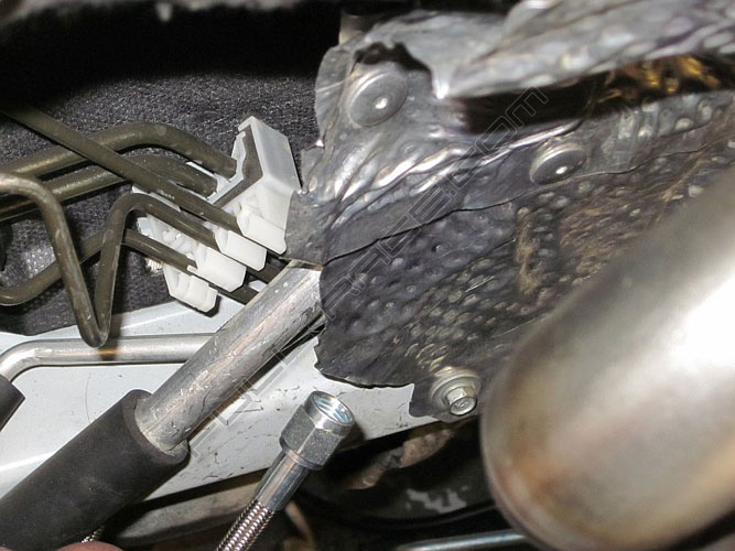
Step 4a: Oil Feed Line
Feed: Right now the engine bay is clear of turbo components and easy to access the firewall so we first want to start by running the oil feed line behind the firewall heatshield. This gives the oil (your turbos most important “lifeblood” connection) a safe path away from the hot exhaust manifold and turbo housings. It is easiest to start on the Right-hand side and feed it through the the left-hand side. There is even a factory clip that holds the line nicely.
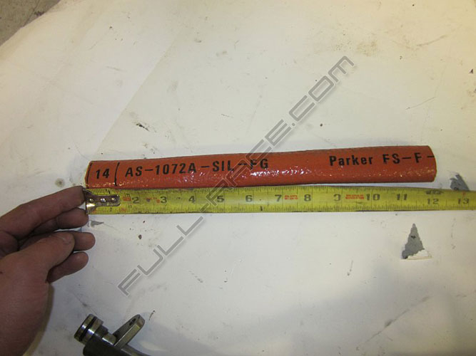
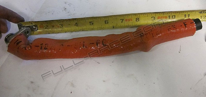
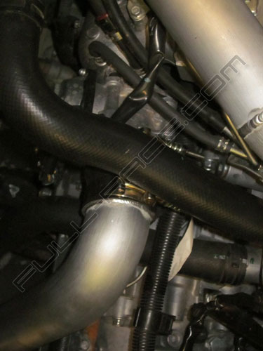
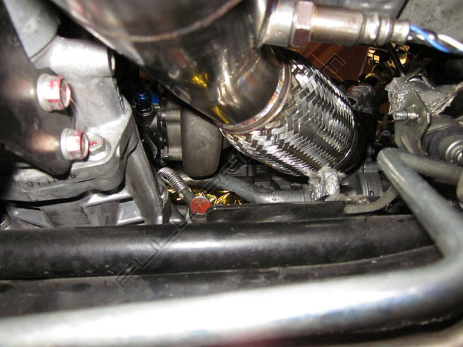
Step 4b: Oil Return Line
The oil return must be insulated from heat given off by the turbo. For this reason we supply insulated heat shield sleeve (orange) and gold foil for maximum thermal protection.
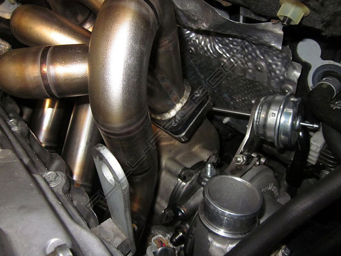
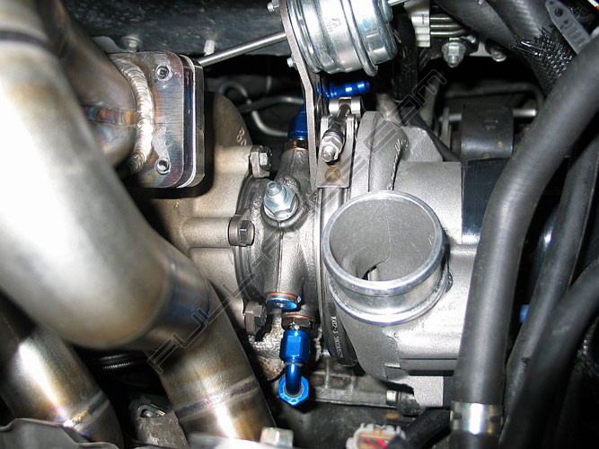
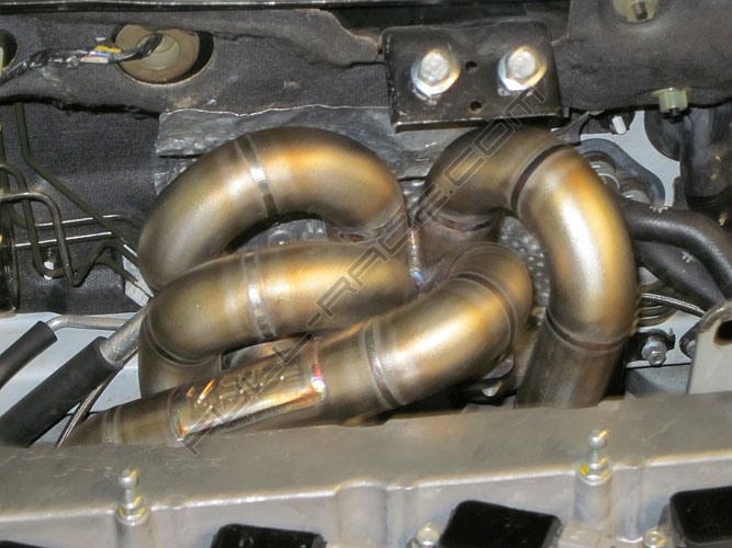
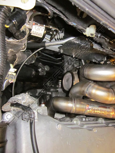
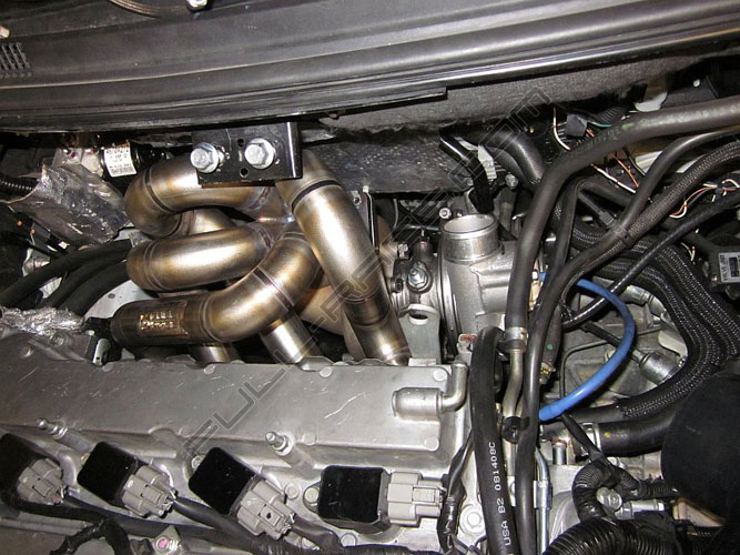
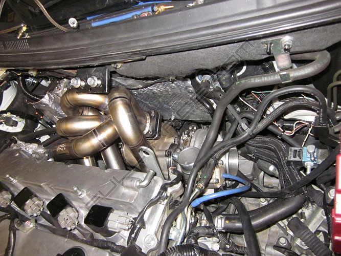
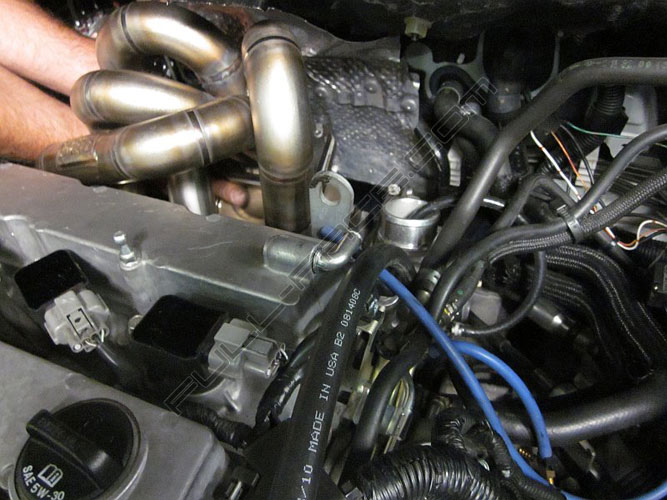
Step 5: Position Turbo & Manifold
The special high temp lock-washers included should remain as pairs – not be separated or lost. They will keep tension on the turbo hardware and make sure the gasket stays leak free, never allowing vibrations or heat cycling to loosen from the manifold. Drop the completely sorted turbo into place, getting ready for manifold installation. Slide the manifold onto the cylinder head, begin to tighten the bolts, and then bolt on the turbo to the manifold. Again – be sure to use anti-seize on all threaded surfaces!
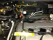
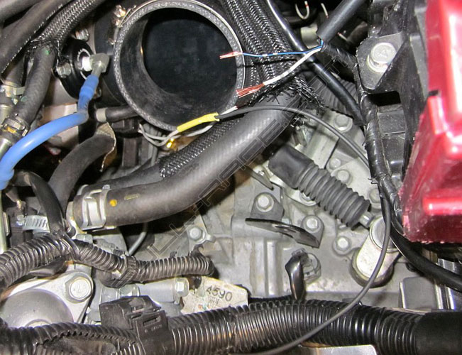
Step 6: Boost Control Solenoid
Wire the built-in Boost Control solenoid. This is VERY simple to connect to the stock ecu, simply wire it directly to the stock ecu by way of replaceing the stock boost solenoid – blue/black wire to one side and white wire to the other – that’s it. Note: spoolinup.com makes GM solenoid plug and play harnesses. This allows you to use all of the the stock wiring when installing the solenoid if you do not like wiring.
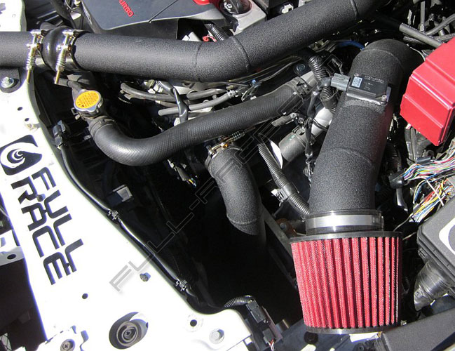
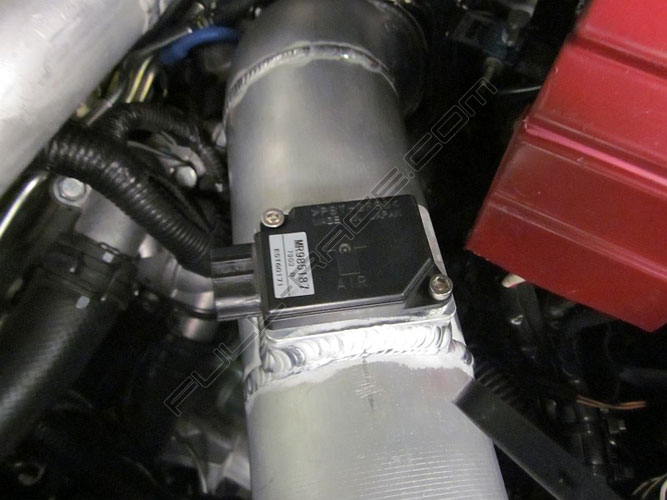
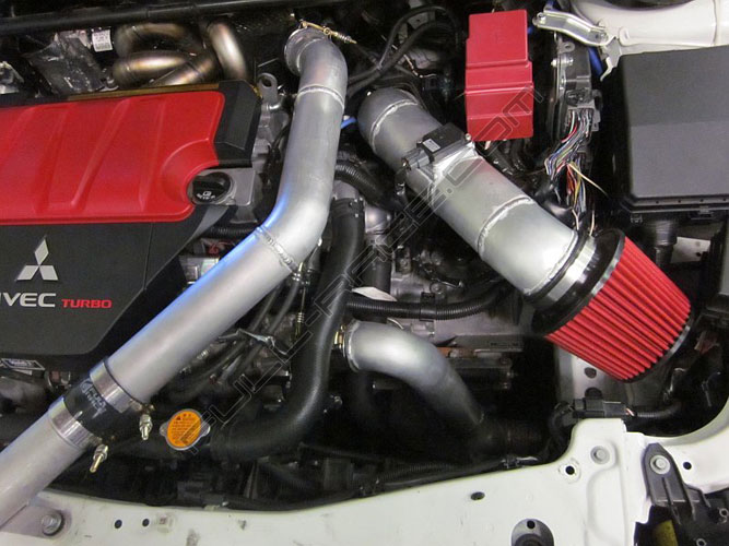
Step 7: 3.5″ MAF Intake
The stock MAF uses only 3″ piping (2.75″ ID) and runs out of airflow headroom at low HP levels. Full-Race’s EFR kit uses what we feel is the optimal solution for this – a true 3.5″ MAF intake that can accurately and efficiently meter air at high horsepower levels and *does not need a recirc BOV* due to the EFR’s integrated compressor bypass valve.
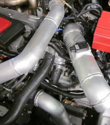
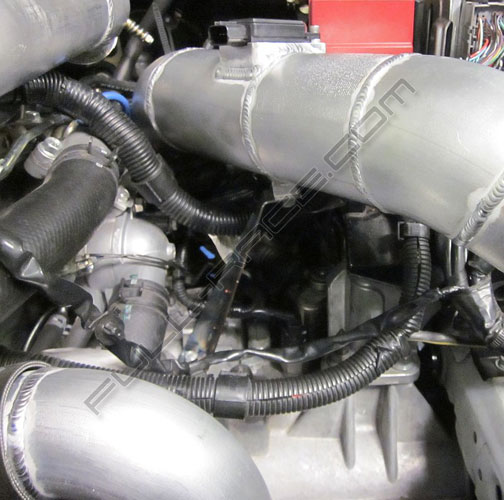
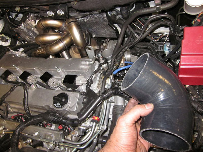
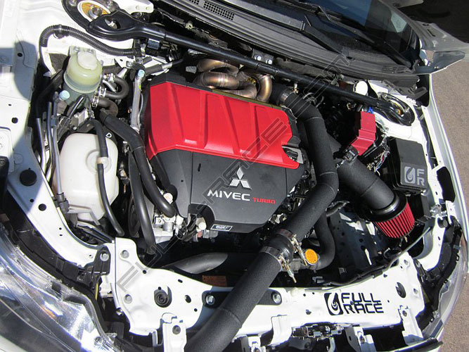
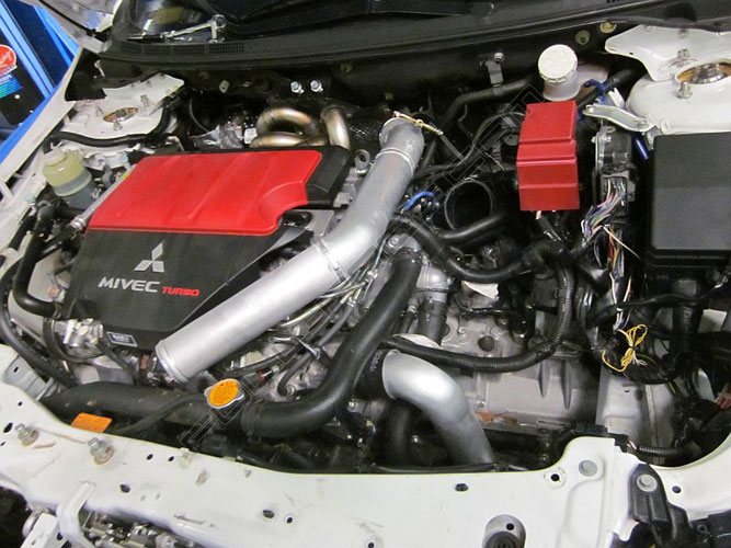
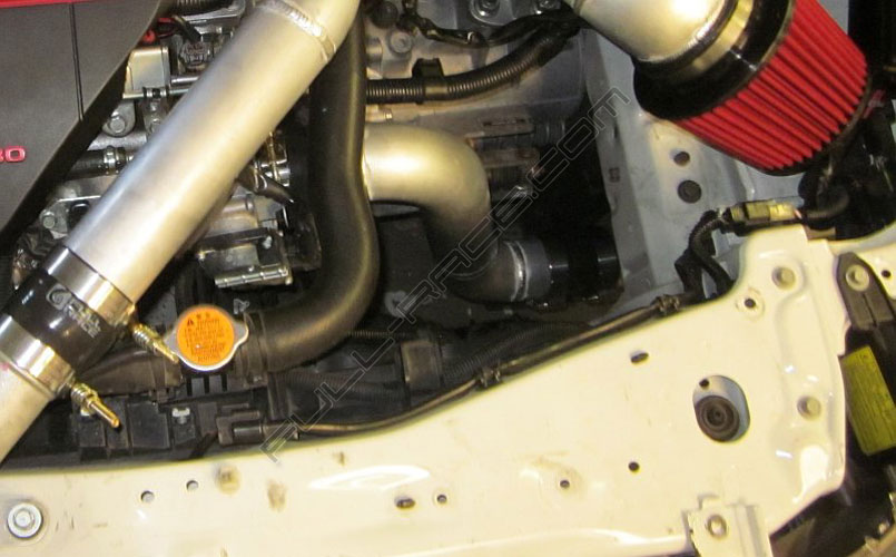
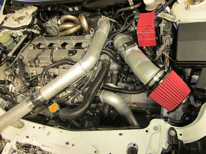
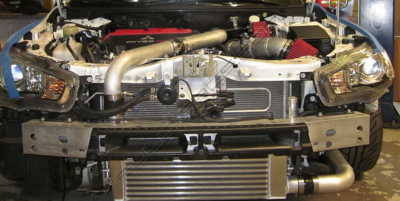
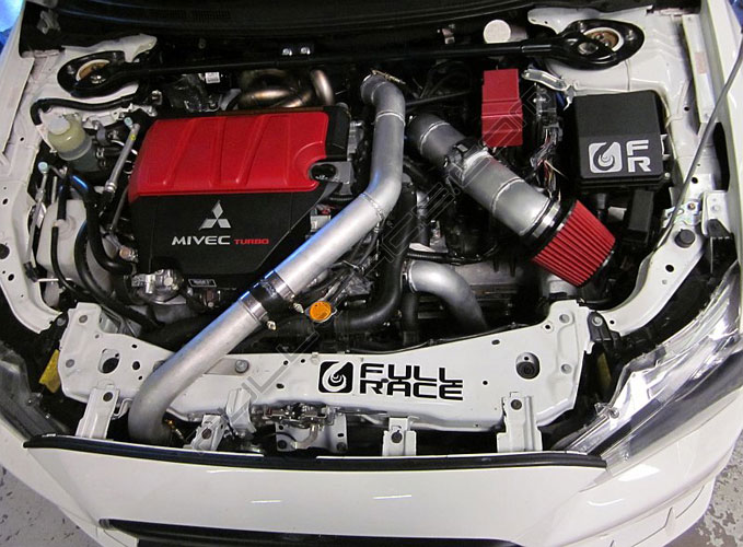
Step 8: Intercooler Charge Piping
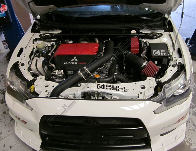
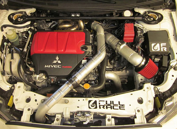
Full-Race’s EvoX charge piping is designed to work with any stock or aftermarket intercooler. Full-Race has an Evo X Intercooler available also. Our charge piping consists of smooth mandrel bent aluminum tubes to shed heat powdercoated black for durable good looks. We utilize thick ply silicone couplers and constant-pressure T-bolt clamps to deliver reliable boost pressure. Start by connecting the Hot side charge piping from Turbo to Intercooler, then connect the intercooler to the throttle body. **note: charge pipes were left raw aluminum to be clearly visible. All turbo kits come with black powdercoat finish for enhanced durability, as seen in the photos at the top of this page.
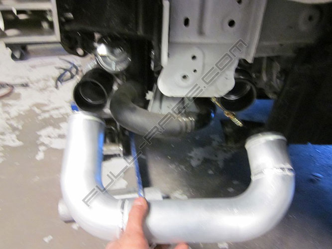
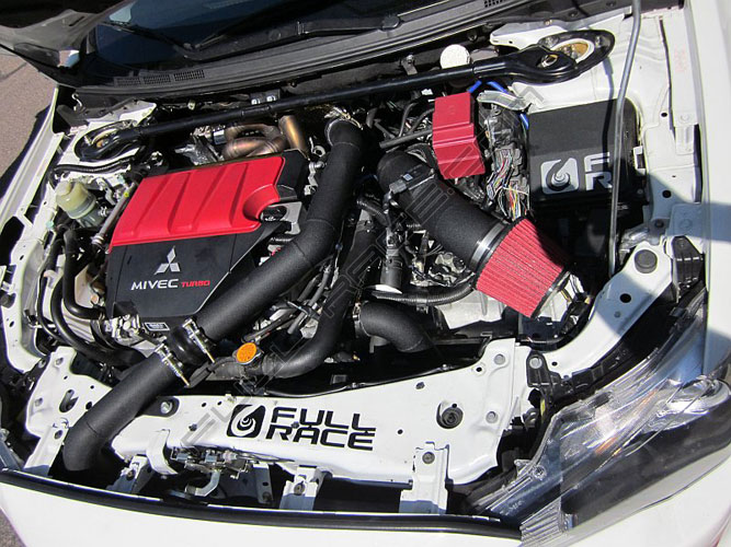
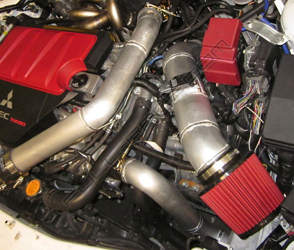
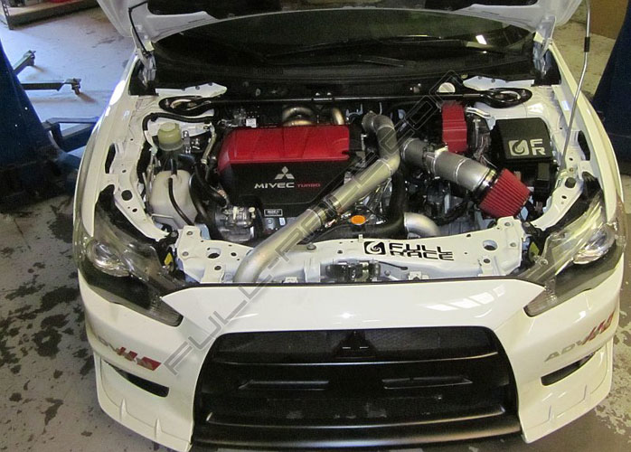
Step 9: Double Check Charge Piping
Look over all couplers/clamps/pipes for clearance and proper orientation ensure that none of the charge pipes are rubbing on any parts of the car or engine and also be sure that none of the couplers or t-bolt clamps are rubbing on anything else. We suggest following the clamp and charge piping positions in the following photos.
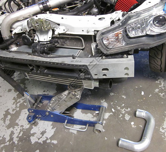
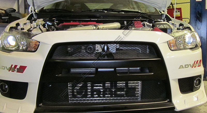
Step 10: Reinstall Front Bumper Cover
Make sure none of the piping or couplers are touching the bumper cover.
Step 11: Connect 3″ Downpipe
The downpipe connects to the turbo using the 3″ vband, in fact this is the easiest part of the install. Make sure the vband’s 10mm nut is easy to access from above AND that it will not interfere with the internal wastegate’s actuator at full open position. We suggest using anti-seize on the inside of the vband clamp and on the threads for the nut as well as the 02 sensor bung.
Notes
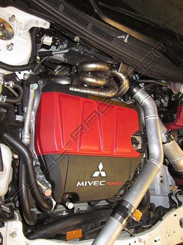
- Full-Race recommends using high temp manifold and downpipe thermal ceramic coatings. Whenever the turbo is located between the engine and firewall there is tremendous heat given off, so ceramic coatings + header wrap can help reduce heat emitted.
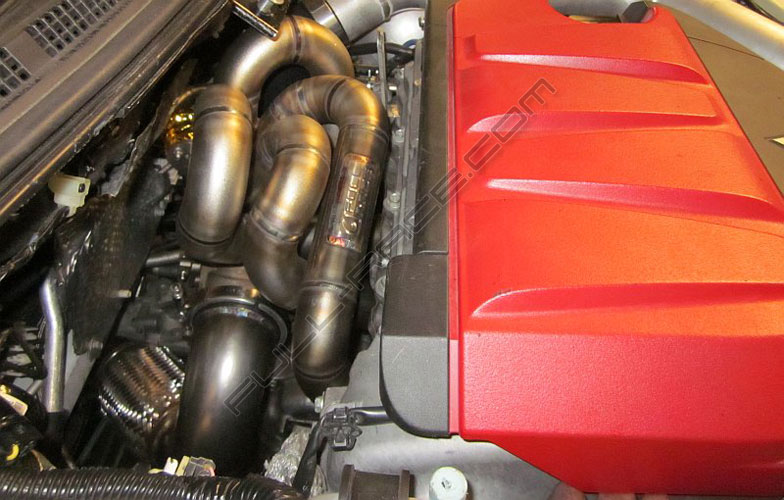
- Black plastic valve covers found on some 2008-09 and all 2010-2011 models should be upgraded to the aluminum valve cover found on most 2008-09 EVO’s (part number 1035A810) when installing any aftermarket EVO 10 Turbo kit. Aftermarket turbo systems create more heat that can cause the plastic cover to melt, distort or even in some severe cases cause a fire.
- Full-Race Evo X manifold and downpipe are suitable to be used with any BorgWarner, Garrett, Precision, Comp, Turbonetics or other turbocharger. *BorgWarner EFR recommended.
- Our 3″ downpipe is compatible with any factory or aftermarket cat-back exhaust system.
- We do not know if this kit will fit RHD EVO X. It may be possible with special downpipe routings
- Full-Race manifold utilizes ideal cylinder pairing, low entry angle merge collectors and the proper implementation of twin scroll technology. The result is significant power and torque increases across the entire power band, while minimizing lag and improving throttle response. Full-Race manufactures each manifold using proprietary robotic TIG welding on thick wall stainless steel, combined with the merge collectors to create a free flowing and highly efficient exhaust path into the turbocharger. All Full-Race manifolds are hand fabricated in the USA.
- If not done already, it is recommended to upgrade the stock 210lph fuel pump to a 400lph Walbro Fuel Pump. This unit is a direct “plug & play” replacement for the Evo X.
- Call or email us with any questions
Videos
Resources
All Articles
For SHOP OWNERs
& KIT BUILDERs
Full-Race Motorsports is the most
trusted name in turbocharging.