
BorgWarner EFR Install Guidelines
BorgWarner EFR Install Guidelines
- Do not use an external oil supply restrictor! All oil flow restriction that is required for the ball bearing and sealing system is accomplished internally within the bearing housing.
- The port on the CRV (recirculation) valve cover must be connected to a pressure source. This hose nipple must see boost pressure when the engine is under boost, and must see vacuum (or lack of boost) in order for the valve to open. In other words, connect the CRV port to the intake manifold. (see figure 2)
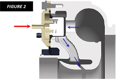
- The BCSV (boost control solenoid valve) flows freely from inlet port to outlet port when it is not energized. The outlet (top-pointing) port must be connected to the wastegate actuator canister (or plugged) in order to not leak boost. When the valve is energized with a PWM signal, some of the boost is “spilled” to the vent port, opposite the elect. connector. (see figure 3)
- The turbo can be re-oriented by loosening the turbine clamp plate bolts (without removing them) and swiveling them out of the way. If the turbo is equipped with a wastegate, the actuator bracket will need to be moved in conjunction with the turbine housing rotation. Changing the orientation of the compressor cover can be done by loosening the v-band. Do not over-torque the clamp plate bolts; only 15ft-lbs is needed. This is especially critical if your EFR turbo is equipped with an aluminum bearing housing.
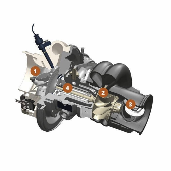
- The water ports are M14x1.5 and only two of the four are needed. The other two should be left plugged. Either orientation can be used, but the water should enter a bottom port, flow across the bearing housing, and exit a top port. (see figure 1)
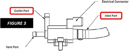
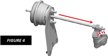
- The EFR turbo is supplied with a “medium boost” actuator canister. This is most appropriate for applications running between 10psi and 20psi of boost. Please refer to the BorgWarner catalog if the “low boost” or “high boost” canisters are needed as component replacements. The actuator should be set with 3mm (3 nut turns) of spring preload after the housing orientation has been completed. Adequate preload is required in order to lift the diaphragm and spring cap away from the lid, and prevents premature failure. More preload (turns) can be added, but this will reduce the available stroke length of the actuator and will limit the available wastegate valve opening amount. (see figure 4)
Generic Turbocharger Installation Precautions
(for all turbos, not EFR only)
- Pre-lube the oil supply and bearing system by cranking the engine without starting.
- Confirm that the exhaust manifold is clean of any debris that could damage the turbine.
- Confirm that the oil drain is within 20 degrees of vertical, is generously sized, and confirm that the crankcase breathing (PCV) system is working properly as to avoid airlock or "gurgling" within the drain path.
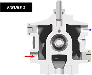
The recirculation valve (CRV) will leak boost if the plastic cap’s nipple is not connected . Boost must be applied to the cap in order to hold the valve closed. If you experience noise from the CRV under part-throttle cruise conditions, we offer an alternate spring: part number 58061191364.
Water flow needs to enter the bearing housing through a bottom port on one side, and exit the top port on the opposite side. Water cooling is particularly critical on EFR turbos equipped with aluminum bearing housings!
Reminder: Do not add an additional oil restrictor (orifice) and use the largest, straightest, and most vertical oil drain tube that you can fit. Confirm a functional PCV system and free crankcase breathing.
Whenever the solenoid valve (BCSV) is not energized, air is free to flow from the inlet port to the outlet port. What this means is the solenoid valve will act as a boost leak if the outlet port is left disconnected or not capped/plugged.
Wastegate control problems can be difficult to diagnose. Here are some common problems and some things that can be done in response:
- Lazy Boost Response
First check for boost leaks, including the CRV and BSCV topics mentioned on this page. Second, consider disabling the wastegate to see what the boost response is while the wastegate function is eliminated. To do this, the canister’s signal hose can be disconnected and plugged or the lever can even be wired or “sprung” shut. Be careful! Don’t rev the engine too high under load because you will overboost! - Boost Creep
Boost creep is defined by having the correct boost setting in the midrange but as you approach redline the boost goes too high. This is very unusual with the EFR system due to the size of the port and the attributes of the wastegate canister. But, if encountered, the best thing to do is drop down to a “lower boost” wastegate canister and then re-tune the preload. - Boost Droop
Boost droop is defined by having the correct boost setting in the midrange but the boost level drops (or “droops”) as you approach redline. The common cure is to add preload by using the lever adjusting nuts and then re-tune the solenoid control system. Some users have used as much as 10mm (10 turns) of preload. Some users find boost droop beneficial as to avoid knock at high rpm.
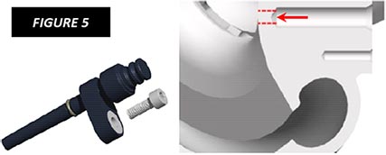
Buying and using our optional speed sensor kit is a good idea, especially if you think you might be pushing your turbo to the limits. To install the speed sensor, carefully remove the compressor cover without damaging the wheel blades and drill the hole the rest of the way through with a 1/4″ drill bit. Deburr the hole where it pierces through the far side and then install the sensor. Electrical details (if needed) can be found in the EFR training guide on BorgWarner's website, www.borgwarnerboosted.com.
This article is also available in PDF.
Republished with permission from BorgWarner Turbo Systems.
Resources
All Articles
For SHOP OWNERs
& KIT BUILDERs
Full-Race Motorsports is the most
trusted name in turbocharging.