
2017+ Honda Civic Type R (FK8) Front Mount Intercooler and Piping Kit Installation

Required Tools:
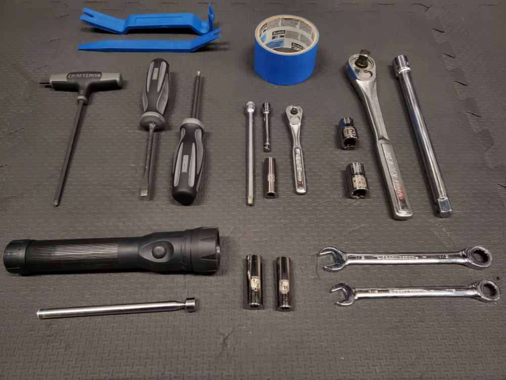
- 1/2 inch drive Ratchet Wrench
- 1/2 inch drive Extension
- 12 mm Socket (1/2 inch drive)
- 14 mm Socket (1/2 inch drive)
- 1/4 or 3/8 inch drive Ratchet Wrench
- 1/4 or 3/8 inch drive Extension
- 10 mm Socket (1/4 or 3/8 inch drive)
- 1/2 inch Socket (1/4 or 3/8 inch drive)
- 7/16 inch deep well Socket (1/4 or 3/8 inch drive)
- 1/2 inch Wrench
- 7/16 inch Wrench
- Flat Tip Screwdriver
- Phillips Screwdriver
- Plastic Trim Removal Tool Set
- Car Ramps (or Jack and Jack Stands)
- Recommended Tools:
- Painters Tape
- Extending Magnet Stick
- Flexible Grabber Claw Tool
Not required but recommended:
91512-SX0-003 (will probably need 3 to replace on the bottom of bumper)
91505-TM8-003 (may want to get spares – used in a lot of places)
2017+ Honda Civic Type R (FK8) Front Mount Intercooler and Piping Kit Installation
Removal:
1) Raise the front of the car to access the underside.
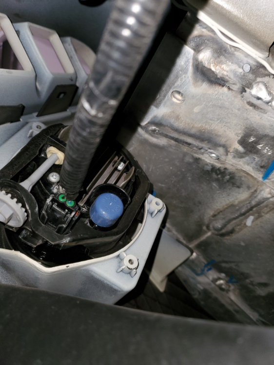
2) Disconnect the negative terminal of the battery.
3) Remove (23) clips holding the Front Bulkhead Cover (74127-TGH-A00) and Rubber Hood Seal (74146-TEA-T00)

4) Gently squeeze and remove the plastic clips on the underside of the Front Bulkhead Cover to remove the intake seal.
5) Remove (10) clips holding the lower side of the Front Bumper Face (04711-TGH-A01ZZ)
6) Remove (6) clips, the (2) 5mm Allen head bolts, and the (2) 10mm bolts holding the Front Bumper (Lower) Plate (71105-TGH-A00).
7) Remove the (10) Phillips head screws from near the tire for the Front (Inner) Fender (Right and Left side) (74101-TGH-A00)

8) Remove the (6) push clips and (2) 10mm bolt from the bottom of Front (Inner) Fender (Right and Left) (74101-TGH-A00)
9) Gently pull the Front (Inner) Fender back and disconnect the wire harness from the back of the fog lights.
10) Remove the (2) Phillips head bolts from the metal Front Cover (Lower) Plate (74114-TGH-A00) and remove the (6) cover bolts by turning them 90 degrees with a Flathead screwdriver.
11) Remove the (4) push clips on the bottom, and the (4) push clips in the wheel wells that hold the Engine (Lower) Cover Assembly (74110-TGH-A00).
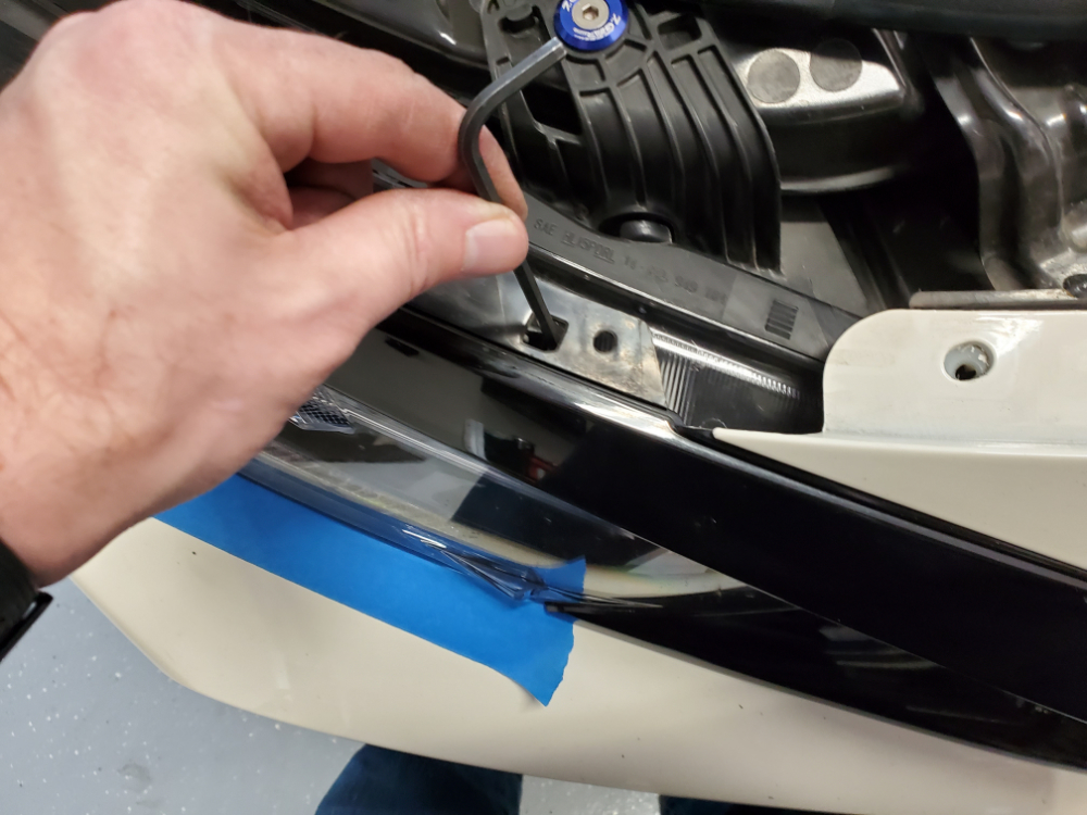
Note: Recommend putting painters’ tape around the bottom of the headlight and along the side of the fender to the side marker. You may also want to remove the side marker light to easily access some of the bumper face clips.
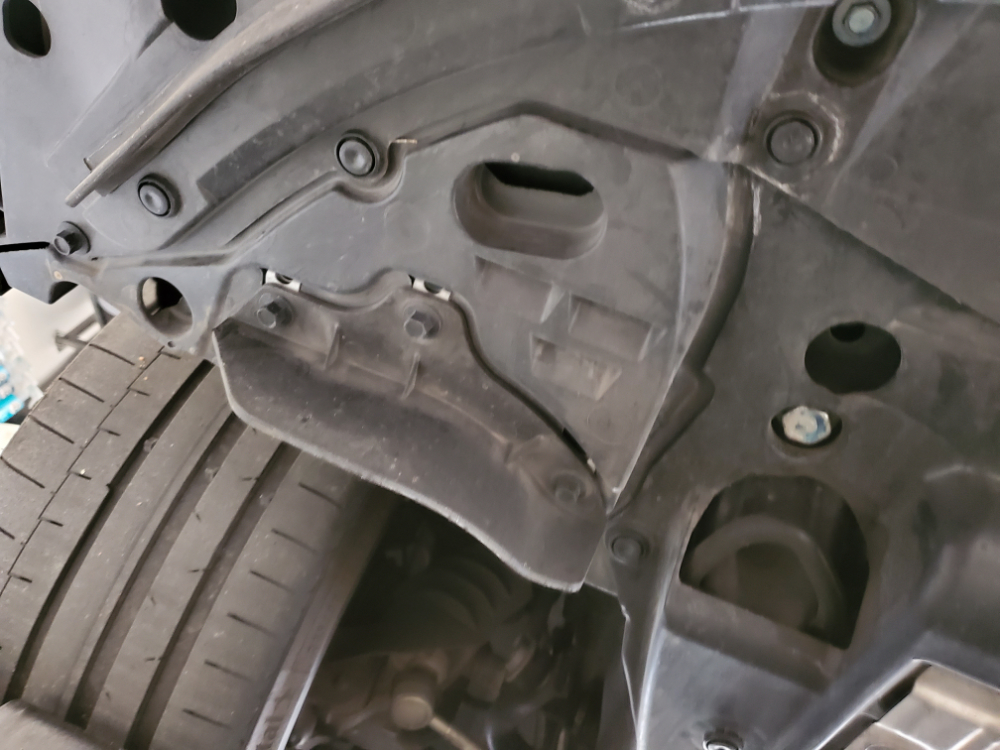
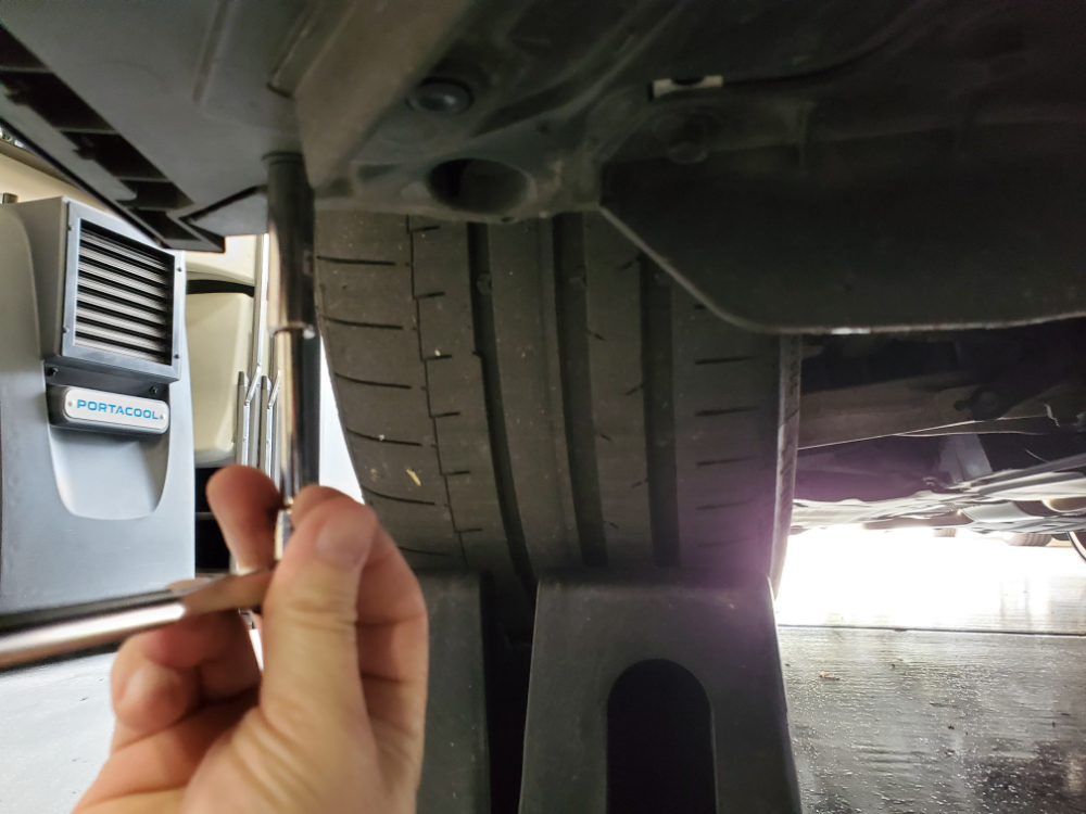
12) Using the straight plastic trim tool push down on the (4) tabs to separate the bumper from the fender. Still using the straight plastic trim tool pry the (2) hook tabs below the headlights upward to separate the bumper from the headlight. (Pictures for Step 12 and 12a show the location of the tabs and hooks behind the bumper.


Note: Use caution for step 13 because if you press down too hard you can break the tabs off.
13) While gently pulling the trim piece above the headlights forward, use a screwdriver or Allen wrench to gently press down to unhook the trim piece from the headlight. There are (2) holes on each side that must be released. You will hear a slight pop when each tab is released.
14) With all the bumper clips and tabs removed/released you can remove the entire Front Bumper Face by gently pulling it forward. Be sure to support the weight so you don’t drop it as it comes loose.

15) With all the bolts and clips removed you can now remove the Front Bumper (Lower) Plate by pulling it forward.
16) Remove the (5) 10mm bolts holding the headlights in place. You will need to use the socket extension for the lower bolts. Gently move the headlights to the side so you can access the Front Bumper Beam (71140-TEA-T00) bolts.


17) Remove the plastic clips that hold the ambient air temperature sensor and wiring to the Front Bumper Beam and move the sensor to the side.

18) Remove the (2) 10mm bolts, (2) 12mm bolts, and (8) 14mm bolts that hold the Front Bumper Beam in place.

19) Remove the OEM Honda intercooler by removing the (2) 10mm bolts for the support brackets, and the (4) 12mm bolts connecting to the intercooler piping. Lift the intercooler then pull forward.

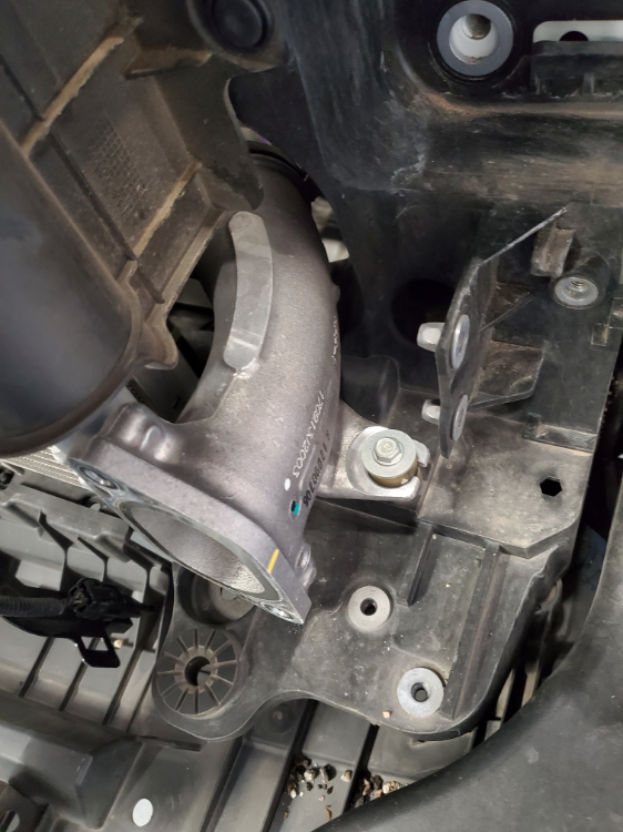
20) Remove the (2) 14mm bolts to remove the Bulkhead (Lower) Brace (71430-TEA-T00) for easier access to the OEM pipe from the turbo (hot side).
21) Loosen the hose clamp and (1) 10mm bolt to remove the hot side pipe.
22) Remove the air filter box. Use the instructions from your air filter box manufacturer.
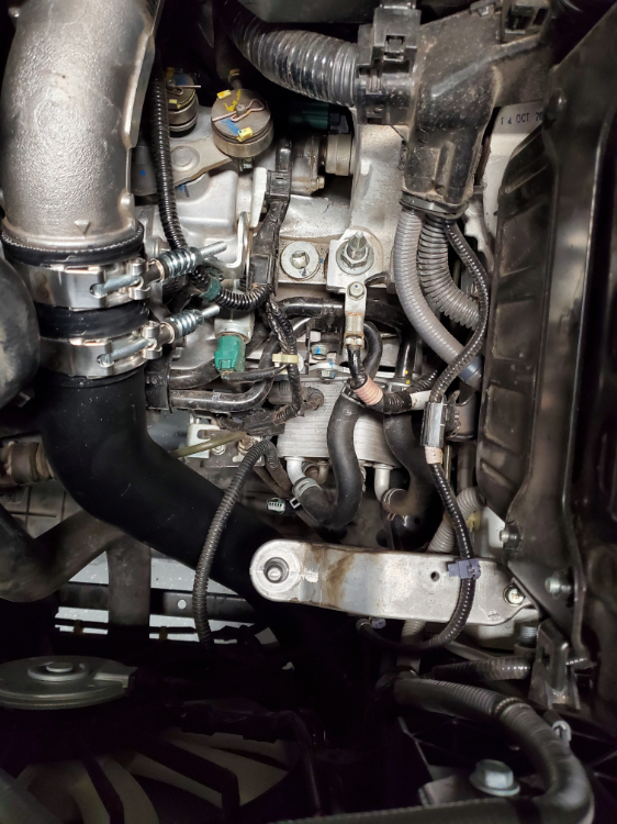
23) Loosen the hose clamp and (1) 10mm bolt to remove the OEM cold side pipe.

Installation:
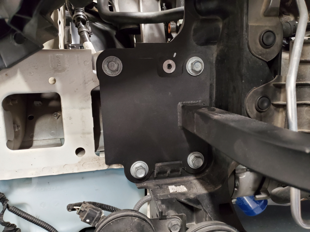
24) Install the steel cross beam with the (8) 14mm bolts that held the OEM Front Bumper Beam.
Note: When aligning the Full Race pipes do not fully tighten the hose clamps until you get everything properly lined up and check for adequate clearance. The pipe ends that go to the intercooler should be straight for proper fitment.
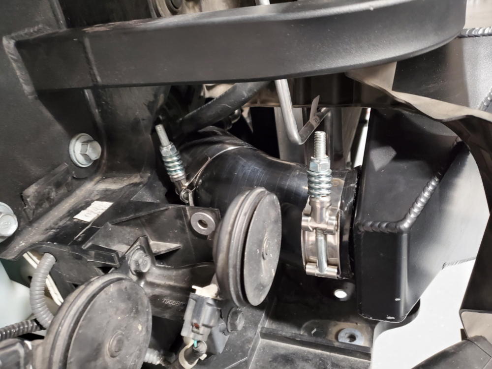
25) Install the reducing straight coupler between the turbo and the shorter Full Race pipe. The smaller side of the reducer goes on the turbo side, with the smaller hose clamp. The larger side of the coupler goes on the bend side of the Full Race pipe.

26) Install one of the angled couplers on the other side of the hot pipe.
27) Install the other straight coupler between the intake pipe and the longer Full Race pipe. The shorter end of the Full Race cold side pipe goes into the straight coupler. The longer straight end goes to the other angled coupler.

Note: Spraying a little bit of window cleaner on the rubber supports will allow the pins on the intercooler to slide in easier. The window cleaner dries without leaving residue.
28) Ensure all pipes are properly placed, aligned, and hose clamps tightened using the 7/16 inch socket or wrench. Mount the intercooler by aligning the pins on the bottom of the intercooler to the rubber mounts. Tilt the top of the intercooler back towards the radiator, ensuring the coupler on the hot and cold side fit properly over the intercooler connections.
29) Tighten the 1/2 inch bolt on the passenger side to secure the intercooler to the steel cross beam. Place the other bolt through the Ambient Air Temperature sensor bracket on the back side of the steel cross beam to secure it in place.

30) Put everything back together in reverse order. The rubber Front Bumper Side Induction Plates (Left and Right) will not be able to attach to the bottom due to the larger intercooler. You can drape them over the intercooler to aid in directing air flow across the intercooler.

Special thanks to Darin Schweitzer for the write up!
Resources
All Articles
For SHOP OWNERs
& KIT BUILDERs
Full-Race Motorsports is the most
trusted name in turbocharging.