
Full-Race 9th Gen Civic Si K24 EFR Turbo Kit Installation
Click Here to view the Full-Race 9th Gen Civic Si K24 EFR Turbo Kit
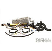
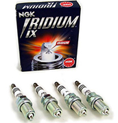
Full-Race turbokits are based on a high grade Investment-Cast stainless steel manifold using a unique velocity stack “bellmouth” shape to provide maximum flow and minimum pressure drop. The items you will need in addition to our turbokit are: 3? exhaust, NGK ILKR8E6 stock number 1422 spark plugs, upgraded clutch/flywheel, injectors, fuel pump and HONDATA Flashpro + map sensor + obd1 IAT sensor. Optional components such as Gauges, electronic boost controller, vacuum block or catch can are optional. Motor mounts will soon be available from quality aftermarket brands such as Hasport and others. Email sales@full-race.com and we can get you a package pricing discount.
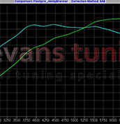
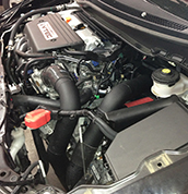
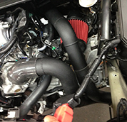
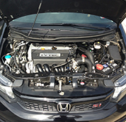
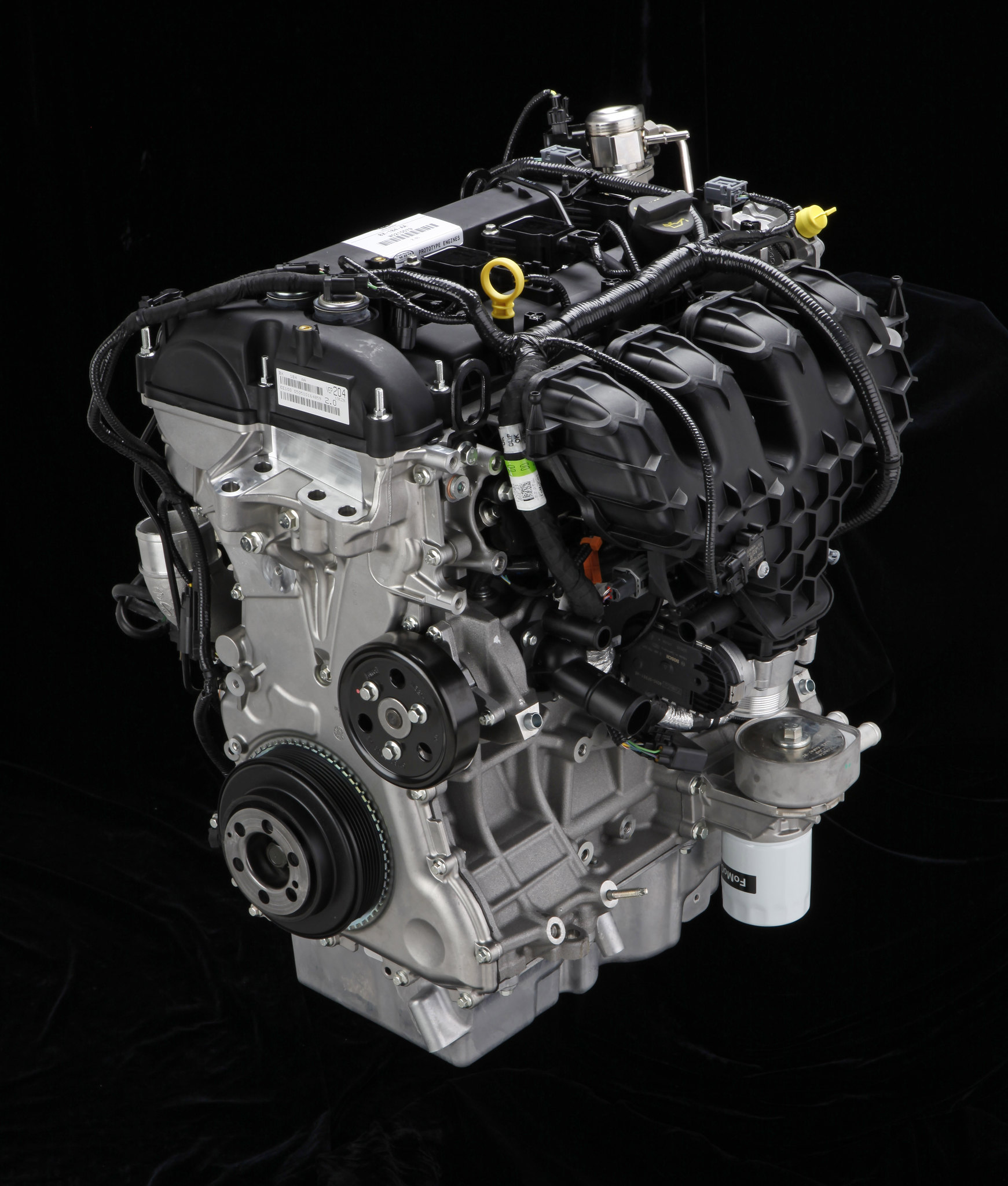
2012 Civic Si, 100% stock K24Z7, EFR7670 turbocharger
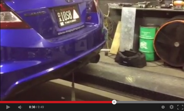
2012 Civic Si Full-Race Exhaust, Full-Race EFR Turbo Kit
Regardless of experience level, properly turbocharging a 9th gen Honda Civic Si can be a rewarding and successful project. These K24Z7 engines are unique with their integrated VTEC cylinder heads and a strong 2.4L bottom end able to reliably generate broad torque and outstanding power – at wastegate pressure on pump gas, using a safe and conservative tune (10-12psi recommended for stock internal K24). One big advantage to using an EFR turbo is they integrate many aspects of turbocharging controls into the turbo – allowing you to start the install by “bench-assembling” the EFR turbocharger and reduce vehicle downtime. Once you know the fuel used and boost level then choose who your tuner will be. We recommend whenever possible going to a local reputable experienced tuner who has experience with turbocharged k series Hondas. It can be helpful to have someone nearby experienced to lend a hand or look over the car should you have any questions.
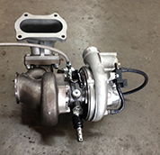
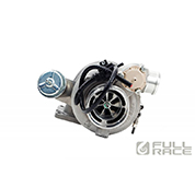
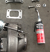
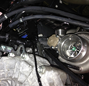
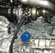
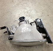
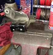
Intro: Aftermarket turbos require you to “clock” the center section and bearing housing to suit the application. In the case of the EFR we also have a wastegate, BOV, coolant/oil feed and drain fittings and boost control all integrated into the turbo – this reduces the amount of parts needed for the install and means we must clock it into position for perfect fitment- prior to attaching the turbocharger to the manifold. Before taking the car apart, prepping the EFR turbo for installation ahead of time saves hours on the install process. Take your time with this, consider starting this step a few nights before you plan to do the install since it will set the stage for everything else to come.
Step 1a: Clock turbo, install fittings: Identically duplicate this turbo clocking position shown below. Reference the coolant fitting locations (in on the bottom and out on the opposite side top) using the supplied aluminum -6AN fittings and crush washers. Make sure to use high temp anti-seize on all turbo hardware and the special high temp lock-washers included should remain as pairs – not be separated or lost. They will keep tension on the turbo hardware and make sure the gasket stays leak free, never allowing vibrations or heat cycling to loosen from the manifold.
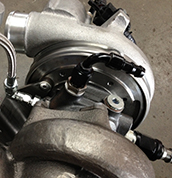


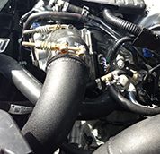
Step 1c: preparing Vacuum Hoses for BOV and boost control: Insert the supplied 3/16? vacuum hose on the BOV, and use a zip tie to keep it in place. Attach the Boost control solenoid’s long vacuum hose to the wastegate’s upper nipple, and slide the clamp in place. The only fastener you will need to adjust later is the Compressor Housings’ vband nut (you can leave this just loose enough to rotate the housing by hand, but tight enough that it isn’t rattling or falling off (we will fully tighten it in the car later, along with the downpipe’s vband clamp). Lastly, if you plan to use an electronic boost control (not required) you can plug the boost control solenoid in now. If no boost control is connected to the solenoid you will simply be running off wastegate pressure all the time.

Once you’ve completed this step, you can slip the 3/8? coolant hose over the -6AN 90degree hose end barbs and use the hose clamps to fasten them securely (do not rely only on the pushlock barbs despite what the hose mfg’s claim!). Now you’re almost ready to take the car apart and start attaching parts to the engine.
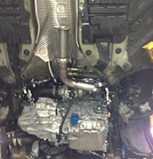
Step 2 (or optionally step 3): Drop Subframe, remove intake, exhaust and downpipe: In order to access the rear and bottom of the engine it will require similar work to doing a clutch install and also removing the downpipe/exhaust – BTW: now is a very good time to upgrade to an aftermarket 06-11 Civic Si clutch and flywheel. Also – unplug all 4 fuel injectors at this point.
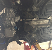

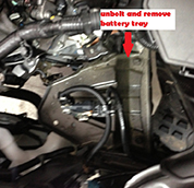
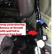
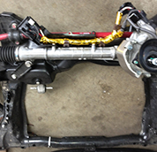
A very short and simplified version of how to unbolt the front subframe from the frame rails and make room to work: First, safely get the car in the air, remove front wheels, lock the steering wheel in place, disconnect and remove the battery. Next, unbolt universal from steering rack splines (leave plastic alignment tab on the steering rack), unplug electric powersteering rack, unbolt lower control arms to separate from their ball joints (but not separating LCA from subframe), pull axles/intermediate shaft, then lastly using a floor jack or a friend, unbolt and lower the subframe. Having a second set of hands can help make this go quickly. (Your first time is always the hardest, it gets easier from there!). Unbolt and remove exhaust/downpipe, but save 02 sensors – you will need to install them on the downpipe later. Remove air cleaner box/intake and you can either leave the rubber snorkel thing in the fender or you can pull the fender to remove it. Examine all motor mounts for any cracks or signs of weakness/sagging. Examine LCA compliance bushings for damage – especially if the car is extremely low. If everything looks good, its time to do some work!
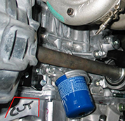
Step 3 (or optionally step 2): Prep For Oil Drain: This can optionally be done as step 2 if you have a second oil pan to prep, helping further reduce downtime but requires an extra oil pan.
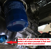
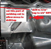
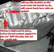
The 2012 Civic Si’s K24Z7 oil pan is more difficult to adapt to turbocharging than most Hondas because they moved the filter on top of where K-series turbo engines typically return their oil. This was a helpful thing from a service standpoint, but requires a little more work when installing a turbo. You can do three options ranging from cutting and tapping the pan to just plain lazy (ghetto-drain not recommend!) and possibly an in-between option we will attempt on our next install. We believe strongly that unbolting the oil pan, cutting/drilling/tapping it, then cleaning out the metal shavings before reinstalling with good sealant (hondabond!) is the only way to go.


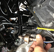
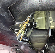
Step 4: Oil Feed
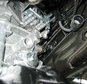
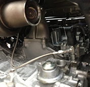
This is a simple one: Remove oil pressure sending unit, install BSPT->NPT adaptor, 1/8? Tee, then -4AN fitting and Oil pressure sending unit on the oil feed tee. Use Teflon thread sealant on all 1/8? tapered threads here. Make sure it is plenty tight and wont leak, but don’t go crazy overtightening like mad.

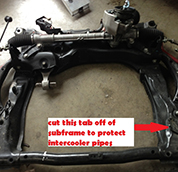
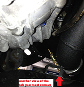
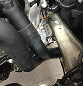
Step 5: prep chassis and subframe, remove extra tabs: When converting this car from NA to turbo, we have to make room for the turbo and intercooler pipes. Cut weight off shift linkage (insert rag in TB inlet and turbo inlet to prevent any metal sparks from entering the engine). Remove the extraneous and unneeded tabs and brackets pictured below:


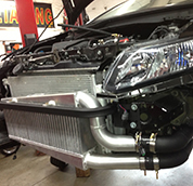
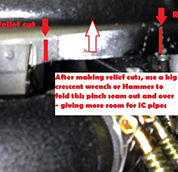
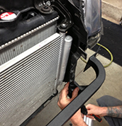
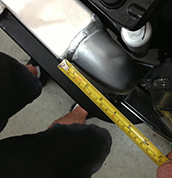
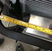
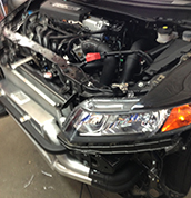
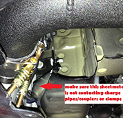
Step 8: Bolt up Intercooler Mount Beam, trim extra sheetmetal under frame rail at charge pipe area, unplug fog lights, unclip and remove bumper cover, unbolt bumper beam, and remove plastic shroud on drivers side in front of radiator/ac condenser. At this point you must make more room for the intercooler pipes by folding the pinch seam out. A big heavy hammer helps make this go fast.


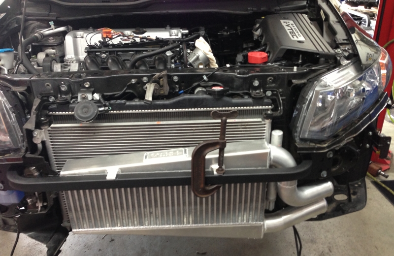

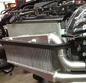
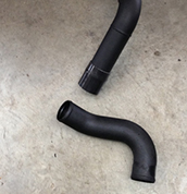

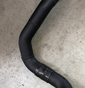
COLDSIDE IC PIPE: Starting @ Lower Intercooler Endtank -> 2.5? coupler -> Larger lower U pipe -> 2.5? coupler -> TB pipe -> 45 degree transition coupler
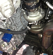
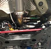
Step 10: Going through the plumbing: A properly primed and leak-free oil feed and drain line are crucial to proper turbocharger health and performance – Triple check your oil fittings at this point since we want the turbo to immediately receive oil pressure upon engine startup. Check -4AN 90 degree oil feed to engine side – make sure it is tightened and will not leak and also tightened at turbo side without rubbing the stainless hose on anything. Measure the oil drain hose, cut it to length, attach it to the fittings, and use hose clamps to tighten.

TB coolant hoses – these hoses are only used to keep the TB warm in freezing cold conditions. For a performance application (especially a turbo one) we don’t want a heated TB – so we will repurpose these ports for the turbo. Intersting Fact: Coolant is used only for keeping heat out of the turbo’s bearings *after the engine is turned off*. When the engine is running, the oil is doing all of the cooling, the coolant has no purpose.Disconnect and attach the upper turbo fitting (coolant return) to upper TB coolant hose port at cyl head using 3/8? hose, attach the lower turbo fitting (coolant feed) to lower TB coolant hose port at cyl head.
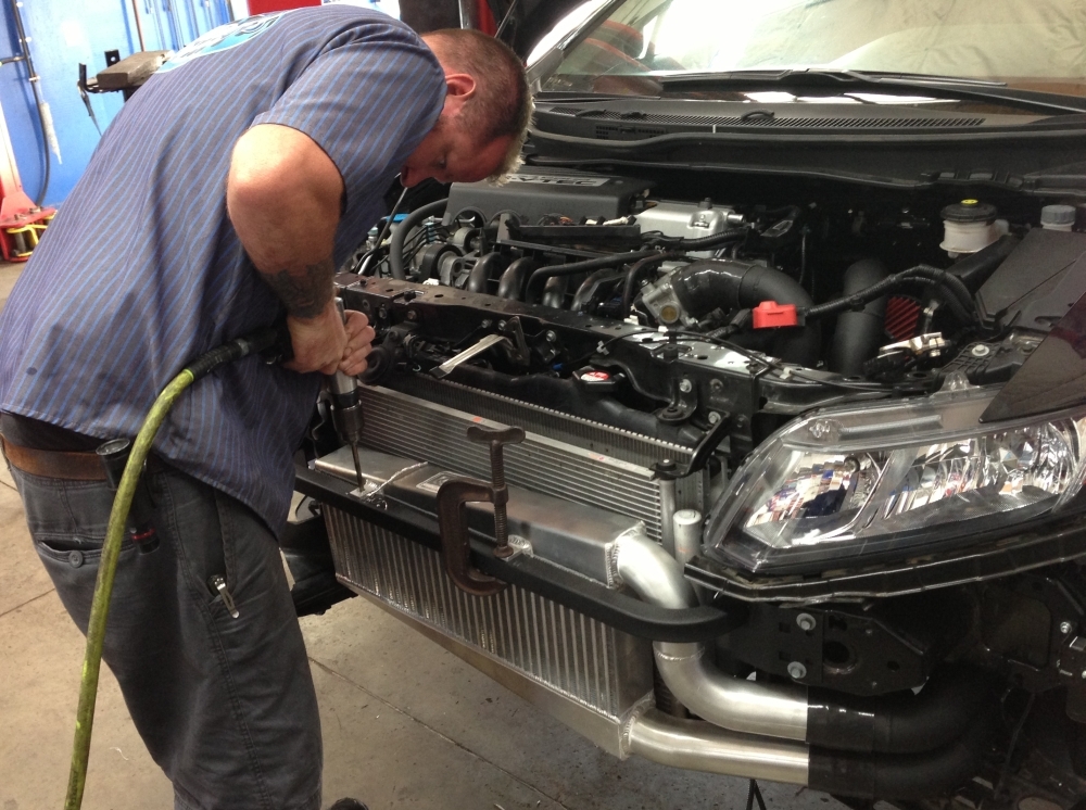
At this point the entire turbokit is installed, and there should be no extra parts. Give everything a double and triple check then get ready – its time put the subframe/steering rack/suspension back on the car.
STEP 11: REINSTALL SUBFRAME/AXLES + INTERMEDIATE SHAFT/ bumper cover

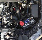
- Rotate battery and fabricate tray (Full-Race stock-location rotated battery tray coming soon!!)
- Go to a lightweight mini battery (just don’t leave it sitting connected for weeks at a time without starting the car)
- Move battery to the trunk: a battery mounted between the rear wheels improves vehicle handling (a good trick to doing this is to get a bmw’s battery cable from a junkyard, almost a perfect fit)


Step 13: Final Details: Install Hondata Flashpro, Fuel Injectors, Fuel Pump, Map Sensor, IAT/MAF and any Gauges: The Hondata FlashPro is a crucial component for proper turbocharging as it connects from your laptop’s USB port to your vehicles diagnostic port to provide real time programming plus a variety of calibration options and extensive datalogging capabilities. It also gives us full control over the new injectors and boost tables.
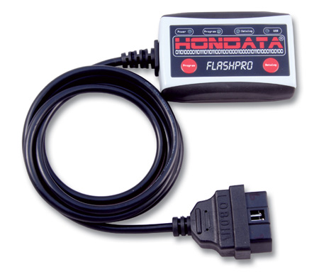

- Install Flashpro: http://www.hondata.com/flashpro_2012si_acura_ilx.html
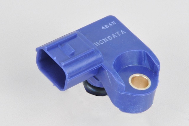
- Swap to the Hondata Map sensor (plug and play)
- Install the deatschworks 65c Fuel Pump
- Gap spark plugs to 0.022-0.024
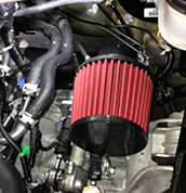
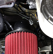
- Install breather filter, or hose/catch can off valve cover
- Install 1/4? check valve in EVAP line to avoid losing any boost to the gas tank. Arrow must point toward the hose going to the engine.
- Install the fuel injectors and Injector plugs – they are NOT polarity specific. Be careful not to confuse which cylinder corresponds to each injector plug
- 2012+ MAF and IAT: The hondata flashpro for the 2012+ Civic Si requires that the MAF remain plugged in at all times. This is different from other year Hondas which allowed it to be removed. However we can intercept the IAT wires and use the obd1 IAT flange on our cold side charge pipe for temperature compensation. Hondata’s how-to is located here: http://www.hondata.com/help/flashpro/index.html?afm_removal.htm
- Full-Race strongly recommends upgrading to the Hasport Rear Motor Mount
Resources
All Articles
For SHOP OWNERs
& KIT BUILDERs
Full-Race Motorsports is the most
trusted name in turbocharging.